- Network Sites:
- Technical Articles
- Market Insights

- Or sign in with
- iHeartRadio


Guide to USB-C Pinout and Features
Join our engineering community sign-in with:, this introductory article will look at some of the most important features of the usb-c standard..
Do you know your way around a USB Type-C connector? This article lays out the anatomy of the USB Type-C pinout and briefly touches on its various modes.
USB Type-C is a specification for a USB connector system that is gaining popularity across smartphones and mobile devices and is capable of both power delivery and data transmission.
Unlike its USB predecessors, it's also flippable—so you don't need to try three times to plug it in.
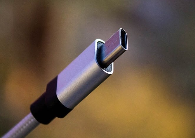
A USB Type-C port. Image courtesy of Denys Vitali
This introductory article will look at some of the most important features of the USB-C standard. Before diving into the pinout and explaining what each is capable of, we'll quickly take a high-level view of what USB-C is and what it's best at.
What Is USB-C?
The USB-C is a relatively new standard which aims to provide high-speed data transfer up to 10Gb/s along with power flow capability of up to 100W. These features can make the USB-C a truly universal connectivity standard for the modern devices.
USB-C or USB Type-C?
These two terms are generally interchangeable (we'll use both throughout this article). Though USB-C is more commonly used, USB Type-C is the official name of the standard as listed on USB.org .
USB-C Features
The USB-C interface has three main features:
- It has a flippable connector. The interface is designed in a way that the plug can be flipped relative to the receptacle.
- It supports USB 2.0, USB 3.0 and USB 3.1 Gen 2 standards. Moreover, it can support third-party protocols such as DisplayPort and HDMI in a mode of operation called Alternate Mode.
- It allows the devices to negotiate and choose an appropriate level of power flow through the interface.
In the following sections, we’ll see how these features are provided by the USB Type-C standard.
The USB Type-C Receptacle/Plug Pins
The USB Type-C connector has 24 pins. Figures 1 and 2, respectively, show the pins for the USB Type-C receptacle and plug.

Figure 1. The USB Type-C receptacle. Image courtesy of Microchip .

Figure 2. The USB Type-C plug. Image courtesy of Microchip .
Usb 2.0 differential pairs.
The D+ and D- pins are the differential pairs used for the USB 2.0 connectivity. There are two D+ pins and two D- pins in the receptacle.
However, the pins are connected to each other and there’s actually only one USB 2.0 data differential pair available for use. The redundancy is included only to provide a flippable connector.
Power and Ground Pins
The VBUS and GND pins are power and the return paths for the signals. The default VBUS voltage is 5 V but the standard allows the devices to negotiate and choose a VBUS voltage other than the default value. The Power Delivery allows VBUS to have a voltage up to 20 V. The maximum current could be also raised up to 5 A. Hence, the USB Type-C could deliver a maximum power of 100 W.
The high power flow could be useful when charging a large device such as a notebook computer. Figure 3 shows an example from RICHTEK where a buck-boost converter is used to generate the appropriate voltage requested by the notebook computer.

Figure 3. Image courtesy of Richtek .
Note that the power delivery technology makes USB Type-C more versatile than the older standards because it makes the power level adaptable with the needs of the load. You can charge both of your smartphone and notebook using the same cable.
The RX and TX Pins
There are two sets of RX differential pairs and two sets of TX differential pairs.
One of these two RX pairs along with a TX pair could be used for the USB 3.0/USB 3.1 protocol. Since the connector is flippable, a multiplexer is required to correctly re-route the data on the employed differential pairs through the cable.
Note that a USB Type-C port could support USB 3.0/3.1 standards but the minimum feature set of USB Type-C doesn’t include USB 3.0/3.1. In such cases, the RX/TX pairs are not used by the USB 3.0/3.1 connectivity and could be used by other USB Type-C functionalities such as the Alternate Mode and the USB Power Delivery protocol. These functionalities may utilize even all of the available RX/TX differential pairs.
The CC1 and CC2 Pins
These pins are the Channel Configuration pins. They perform a number of functions such as cable attachment and removal detection, receptacle/plug orientation detection, and current advertisement. These pins could be also used for the communications required by the Power Delivery and Alternate Mode.
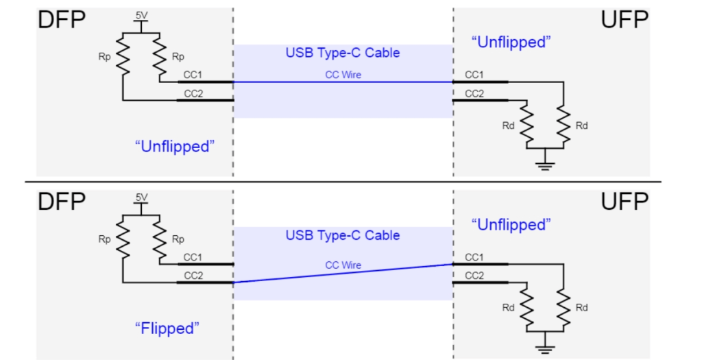
Figure 4 below shows how the CC1 and CC2 pins reveal the receptacle/plug orientation. In this figure, DFP stands for Downstream Facing Port which is the port acting as either the host in data transmission or the source for power. UFP denotes Upstream Facing Port which is the device connected to the host or the power consumer.
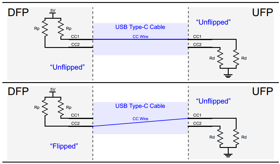
Figure 4. Image courtesy of Microchip .
The DFP pulls up the CC1 and CC2 pins through the Rp resistors but the UFP pulls them down through Rd. If no cable is attached, the source sees a logic high at CC1 and CC2 pins. Connecting the USB Type-C cable creates a current path from 5-V supply to ground. Since there’s only one CC wire inside the USB Type-C cable, only one current path is formed. For example, in the upper graphic of Figure 4, the CC1 pin of the DFP is connected to the CC1 pin of the UFP. Hence, the DFP CC1 pin will have a voltage lower than 5 V but the DFP CC2 pin will be still at the logic high. Therefore, monitoring the voltage on the DFP CC1 and CC2 pins, we can determine cable attachment and its orientation.
In addition to the cable orientation, the Rp-Rd path is used as a way of communicating information about the source current capabilities. To this end, the power consumer (UFP) monitors the voltage on the CC line. When the voltage on the CC line has its lowest value (about 0.41 V), the source can provide the default USB power which is 500 mA and 900 mA for the USB 2.0 and USB 3.0 respectively. When the CC line voltage is about 0.92 V, the source can provide a current of 1.5 A. The highest CC line voltage which is about 1.68 V corresponds to the source current capability of 3 A.
The VCONN Pin
As mentioned above, the USB Type-C aims to provide blazing fast data transfer speeds along with high levels of power flow. These features may require the use of special cables that are electronically marked by employing a chip inside. Besides, some active cables utilize a re-driver chip to strengthen the signal and compensate for the losses incurred by the cable, etc. In these cases, we can power the circuitry inside the cable by applying a 5-V, 1-W power supply to the VCONN pin. This is shown in Figure 5.
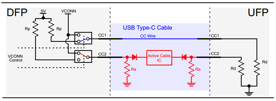
Figure 5. Image courtesy of Microchip .
As you can see, the active cable uses the Ra resistors to pull down the CC2 pins. The value of Ra is different from Rd so the DFP is still able to determine the cable orientation by examining the voltage on the DFP CC1 and CC2 pins. After determining the cable orientation, the channel configuration pin corresponding to the “Active Cable IC” will be connected to a 5-V, 1-W supply to power the circuitry inside the cable. For example, in Figure 5, the valid Rp-Rd path corresponds to the CC1 pin. Hence, the CC2 pin is connected to the supply denoted by VCONN.
The SBU1 and SBU2 Pins
These two pins correspond to low-speed signal paths that are used only in the Alternate Mode.
The USB Power Delivery
Now that we are familiar with the pinning of the USB-C standard, let’s have a brief look at the USB Power Delivery.
As mentioned above, the devices using the USB Type-C standard can negotiate and choose an appropriate level of power flow through the interface. These power negotiations are achieved through a protocol called USB Power Delivery which is a single wire communication over the CC line discussed above. Figure 6 below shows an example USB Power Delivery where the sink sends requests to the source and adjusts the VBUS voltage as needed. At first, a 9-V bus is requested. After the source stabilizes the bus voltage at 9 V, it sends a “power-supply-ready” message to the sink. Then, the sink requests a 5-V bus and the source provides it and sends a “power-supply-ready” message again.

Figure 6. Image courtesy of Richtek .
It’s important to note that the “USB Power Delivery” is not just about the power delivery related negotiations, other negotiations, such as those related to the Alternate Mode, are done using the Power Delivery protocol on the CC line of the standard.
Alternate Modes
This mode of operation allows us to implement third-party protocols, such as DisplayPort and HDMI, using the USB Type-C standard. All Alternate Modes must at least support a USB 2.0 and USB Power Delivery connection. For more information, please refer to this TI document .
The USB Type-C has interesting features. It supports a blazing fast data transfer speed of up to 10 Gb/s and high power flow of up to 100 W. These along with a flippable connector can make the USB Type-C a truly universal standard for the modern devices.
To see a complete list of my articles, please visit this page .
Related Content
- Practical Guide to RF Testing Secure Radios
- Architecture to Circuit Schematics in 60 Seconds: An Introduction to Circuit Mind AI
- A Starter Guide to 2020 RoHS Compliance
- A Guide to Industry Tech Days 2021
- How to Ensure MultiGigabit Automotive Ethernet Compliance
- How To Make A 5V To 15 KV High Frequency Inverter Using An Old SMPS Power Supply
Learn More About:
- USB Power Delivery
- usb type-c alternate mode
You May Also Like

IoMT: The Next Electronic Engineering Revolution And Its Featured Devices
In Partnership with Future Electronics

Siemens Unveils 3-Piece Emulation and Prototyping Solution
by Jake Hertz

SureCore Balances Power and Cooling Costs With Cryogenic Memory
by Arjun Nijhawan
Researchers Create World’s First Graphene Semiconductor

STMicro, ADI, and Rohm Release New Op Amps for Industrial Applications
by Aaron Carman

Welcome Back
Don't have an AAC account? Create one now .
Forgot your password? Click here .


USB TYPE-C Connector
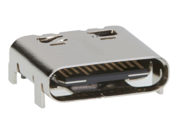
[Click the image to enlarge it]
USB TYPE-C is a new port designed for high speed data exchange and high power deliver capability. The first thing to realize is that USB TYPE-C is not a new USB standard like USB1.0, USB2.0 , USB3.0, and USB3.1. Those are protocols defining speed and other features, whereas USB TYPE-C is all about physical connection.
USB TYPE-C specification was published by USB Implementers Forum (USB-IF) and was finalized in August 2014. It is a 24 pin USB connector , which is distinguished by its two-fold rotationally-symmetrical connector as shown in above picture.
USB -C connector is designed for replacing USB-A and USB-B connectors. It is also designed for supporting USB3.1 standard fully. It is now poised to become the universal port.
USB Type-C Pin Configuration
As mentioned earlier USB-C is a 24 pin connector and we will describe the each pin below.
|
|
|
|
| A1 | GND | Ground |
| A2 | SSTXp1 | Super Speed differential pair 1, TX, positive |
| A3 | SSTXn1 | SuperSpeed differential pair 1, TX, negative |
| A4 | VBUS | Bus power |
| A5 | CC1 | Configuration channel |
| A6 | Dp1 | USB 2.0 differential pair 1, positive |
| A7 | Dn1 | USB 2.0 differential pair 1, negative |
| A8 | SBU1 | Side Band Use (SBU) |
| A9 | VBUS | Bus power |
| A10 | SSRXn2 | Super Speed differential pair 4, RX, negative |
| A11 | SSRXp2 | Super Speed differential pair 4, RX, positive |
| A12 | GND | Ground |
| B1 | GND | Ground |
| B2 | SSTXp2 | Super Speed differential pair 3, TX, positive |
| B3 | SSTXn2 | Super Speed differential pair 3, TX, negative |
| B4 | VBUS | Bus power |
| B5 | CC2 | Configuration channel |
| B6 | Dp2 | USB 2.0 differential pair 2, positive |
| B7 | Dn2 | USB 2.0 differential pair 2, negative |
| B8 | SBU2 | Side Band Use (SBU) |
| B9 | VBUS | Bus power |
| B10 | SSRXn1 | Super Speed differential pair 2, RX, negative |
| B11 | SSRXp1 | Super Speed differential pair 2, RX, positive |
| B12 | GND | Ground |
The awkward fumble over connecting a pen drive to USB port is finally over with USB-C. The orientation needs to be correct for connecting a pen drive to a USB-A port where as in USB-C port it is not necessary. You can connect devices irrespective of orientation to the USB-C and the port will auto detect the device. So USB TYPE-C is reversible port. Also USB-C is to replace both USB-A and USB-B, so connectivity at both PC and SMART PHONE remains the same. We can connect any end of the cable to PC or SMART PHONE. The issue of connecting correct end of the cable to the PC or MOBILE will be solved permanently with USB-C port.
Features and Electrical Characteristics
- High data transfer speeds up to 10Gb/s
- Up to 5Amp current handling capacity
- Reversible plug orientation and cable direction
- Small size similar to USB2.0 micro-B
- Designed to establish future USB performance needs
- USB-C can replace video ports like VGA and HDMI to provide high quality video output. It can deliver Ultra HD (4K) video for good gaming and movie experience
- USB-C can also replace audio output or 3.5mm jack to provide high quality audio or music in your smart phone or tablet
- USB-C can also replace Ethernet port to provide high speed internet up to 1000Mb/s
- USB-C can also replace SD card port, power port and all other to truly become universal port.
- Operating temperature: -30ºC to +85ºC
Note: Complete technical details can be found in the USB Type-C Connector Datasheet , linked at the bottom of this page.
Brief About USB TYPE-C
USB-C has become the new trend after its introduction. All the latest Laptops, Notebooks, Smart phones, Peripherals, Tablets and Memory devices are tend to be installed with USB-C. We can see new MACBOOK has only a single USB-C port to replace all other ports. In MACBOOK all the functions are done by that single port. Also GOOGLE CHROME BOOK PIXEL and new smart phones are having USB-C to promote for its application in all other areas.
How to use the USB TYPE-C
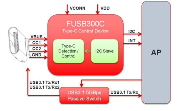
As mentioned earlier the features provided by USB-C are many. With so many features in a single port comes with complex management. So we need a port controller for using USB-C port. There are different controllers available in the market like TPS65982, FUSB300C and UPD360. We have to choose the appropriate controller depending on the requirement. A typical internal circuitry for USB-C is given below.
Applications
- Laptops and Notebook
- Personal Computers
- Tablets and Music players
- Printers and Scanners
- Digital cameras
- LCD and LED monitors
- Set top boxes
- Factory automation
- Medical devices
- Data centers
- Power packs and chargers
- Industrial machinery
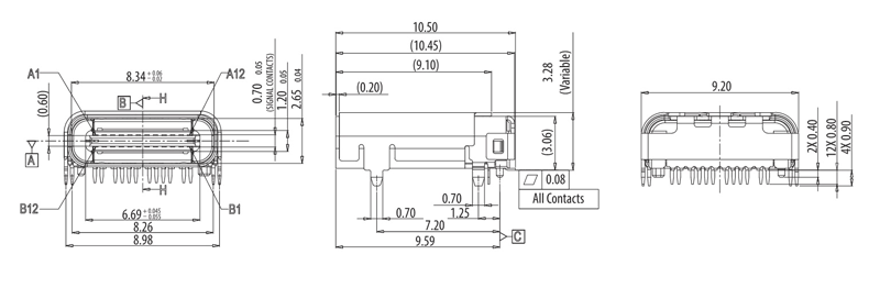
2-D Model and Dimensions
All measurements are in millimeter
Related Post
Join 20k+subscribers.
We will never spam you.
Be a part of our ever growing community.

RECOM Power’s 10 W AC/DC converters in a 1.8” x 1.0” case are ideal for EV charging applications

The ECX-31B tuning fork crystal brings efficiency to mobile, industrial and wireless applications.

TE Connectivity's UAM Wi-Fi Triple Band Antennas offer a compact alternative for terminal antennas

onsemi's op amp is suitable for both high-side and low-side current sensing applications

3W-40W PCB mount Medical AC-DC Power Supplies for Class II and BF-rated medical applications

Hammond’s RM series aluminum cases are suitable for 19” rackmount or desktop/benchtop applications.

T6793 CO2 sensor module is designed for applications requiring high-performance in a compact package
The EMC product range includes PCB and Cable ferrites, inductors, capacitors, and more...
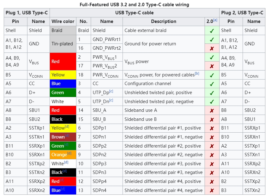
serial cable wiring
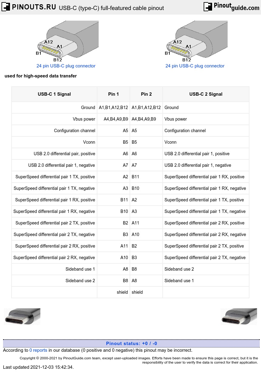
Usb-c (type-c) full-featured cable pins and signals.

- Ask a question
USB type-C cable
Full-featured USB-C cables that implement USB 3.1 Gen 2 can handle up to 10 Gbit/s data rate at full duplex. They are marked with a SuperSpeed+ (SuperSpeed 10 Gbit/s) logo. There are also USB-C cables which can carry only USB 2.0 with up to 480 Mbit/s data rate . All USB-C cables must be able to carry a minimum of 3 A current (at 20 V, 60 W) but can also carry high-power 5 A current (at 20 V, 100 W). Full-featured USB Type-C cables are active, electronically marked cables that contain a chip with an ID function based on the configuration data channel and vendor-defined messages (VDMs) from the USB Power Delivery 2.0 specification. USB Type-C devices also support power currents of 1.5 A and 3.0 A over the 5 V power bus in addition to baseline 900 mA; devices can either negotiate increased USB current through the configuration line, or they can support the full Power Delivery specification using both BMC-coded configuration line and legacy BFSK-coded VBUS line.
Alternate Mode dedicates some of the physical wires in the Type-C cable for direct device-to-host transmission of alternate data protocols. The four high-speed lanes, two sideband pins, two USB 2.0 pins and one configuration pin can be used for Alternate Mode transmission. The modes are configured using vendor-defined messages through the configuration channel.
| USB-C 1 Signal | Pin 1 | Pin 2 | USB-C 2 Signal |
|---|---|---|---|
| Ground | A1,B1,A12,B12 | A1,B1,A12,B12 | Ground |
| Vbus power | A4,B4,A9,B9 | A4,B4,A9,B9 | Vbus power |
| Configuration channel | A5 | A5 | Configuration channel |
| Vconn | B5 | B5 | Vconn |
| USB 2.0 differential pair, positive | A6 | A6 | USB 2.0 differential pair 1, positive |
| USB 2.0 differential pair 1, negative | A7 | A7 | USB 2.0 differential pair 1, negative |
| SuperSpeed differential pair 1 TX, positive | A2 | B11 | SuperSpeed differential pair 1 RX, positive |
| SuperSpeed differential pair 1 TX, negative | A3 | B10 | SuperSpeed differential pair 1 RX, negative |
| SuperSpeed differential pair 1 RX, positive | B11 | A2 | SuperSpeed differential pair 1 TX, positive |
| SuperSpeed differential pair 1 RX, negative | B10 | A3 | SuperSpeed differential pair 1 TX, negative |
| SuperSpeed differential pair 2 TX, positive | B2 | A11 | SuperSpeed differential pair 2 RX, positive |
| SuperSpeed differential pair 2 TX, negative | B3 | A10 | SuperSpeed differential pair 2 RX, negative |
| SuperSpeed differential pair 2 RX, positive | A11 | B2 | SuperSpeed differential pair 2 TX, positive |
| SuperSpeed differential pair 2 RX, negative | A10 | B3 | SuperSpeed differential pair 2 TX, negative |
| Sideband use 1 | A8 | B8 | Sideband use 2 |
| Sideband use 2 | B8 | A8 | Sideband use 1 |
| shield | shield |
Coaxial wire construction should be used for all SDP’s and there are no drain wires. The shields of the coaxial wires are connected to the ground pins. If shielded twisted pair is used, then drain wires are needed and shall be connected to the GND pins. Pin B5 (Vconn) of the USB Type-C plug shall be used in electronically marked versions of this cable. Pins B6 and B7 should not be present in the USB Type-C plug. All Vbus pins shall be connected together within the USB Type-C plug. A 10 nF bypass capacitor is required for the Vbus pin in the full-featured cable at each end of the cable. Shield and all GND shall be connected within the USB Type-C plug on both ends of the cable assembly.
Maximum cable length is 2 meters.
The USB Type-C Power-Only plug is a depopulated version of the USB Full-Featured Type-C plug or the USB 2.0 Type-C plug . Contacts for configuration channel, Vbus, and GND (i.e., A1, A4, A5, A9, A12, B1, B4, B9, and B12) shall be present, others are optional. Implementation of resistor or CC communication on pin A5 is required.
- USB-C (Type-C) pinout

The Ultimate Guide to USB-C Pinout and Features: Unleashing the Power of Universal Connectivity
Introduction:.
The USB-C connector has revolutionized the way we connect and transfer data between devices, offering a universal solution for a wide range of devices. With its compact size and versatile capabilities, USB-C has become the standard for modern devices, including laptops, smartphones, tablets, and even gaming consoles. In this comprehensive guide, we will explore the pinout and features of USB-C, shedding light on its potential and how it has transformed the way we interact with technology.
Understanding USB-C:
USB-C, also known as USB Type-C, is the latest iteration of the USB (Universal Serial Bus) standard. It was introduced by the USB Implementers Forum (USB-IF) to replace various types of USB connectors, including the standard USB-A and USB-B connectors. Unlike its predecessors, USB-C features a reversible design, meaning it can be plugged in either way, eliminating the frustration of trying to align the connector correctly.
Pinout of USB-C:
The USB-C connector consists of 24 pins, each serving a specific purpose to enable various functionalities. These pins are divided into different groups, including power delivery, data transmission, and audio/video capabilities. Let’s explore the key pins and their functionalities:
VBUS (Voltage Bus):
This pin provides power to the connected device, allowing it to charge or be powered by another device.
It supports power delivery up to 100W, making it suitable for charging laptops and other power-hungry devices.
CC (Configuration Channel):
The CC pins are used for communication and negotiation between devices.
They enable the devices to determine each other’s capabilities and establish the appropriate power and data transfer modes.
D+/D- (Data+ and Data-):
These pins are responsible for data transfer between devices.
They support USB 2.0, USB 3.1, and even Thunderbolt 3 protocols, enabling high-speed data transfer rates.
SBU (Sideband Use):
The SBU pins are used for alternate mode functionalities, such as DisplayPort or HDMI output.
They enable USB-C to transmit audio and video signals, expanding its capabilities beyond data transfer.
Features of USB-C:
- Reversible Design:
One of the most significant advantages of USB-C is its reversible design, eliminating the frustration of trying to plug in the cable correctly.
This feature enhances user experience and convenience, making it easier to connect devices without worrying about the orientation of the connector.
- Faster Data Transfer:
USB-C supports USB 3.1 and Thunderbolt 3 protocols, offering significantly faster data transfer rates compared to previous USB versions.
With USB 3.1, data transfer speeds of up to 10 Gbps can be achieved, enabling quick and efficient file transfers.
- Power Delivery:
USB-C supports power delivery up to 100W, allowing devices to charge rapidly.
This feature is particularly beneficial for laptops and other power-hungry devices that require fast charging capabilities.
- Audio/Video Capabilities:
USB-C can transmit audio and video signals through alternate modes, such as DisplayPort or HDMI.
This enables users to connect their devices to external monitors or TVs, expanding their capabilities beyond data transfer.
Conclusion:
USB-C has emerged as a game-changer in the world of connectivity, offering a versatile and powerful solution for modern devices. With its reversible design, faster data transfer rates, power delivery capabilities, and audio/video functionalities, USB-C has become the go-to connector for a wide range of devices. Its widespread adoption by device manufacturers and its ability to unify various connectivity standards have made USB-C an integral part of our daily lives. As technology continues to evolve, USB-C will undoubtedly play a crucial role in shaping the future of universal connectivity.
Share Article:
Aravind s s, raspberry pi 4 gpio pinout, max30102 pulse oximeter and heart-rate sensor for wearable health, leave a reply cancel reply.
Save my name, email, and website in this browser for the next time I comment.
USB C Pinout & Features Explained
USBs have become a vital part of our day-to-day life. The wide range of applications includes interfacing, power delivery, data storage, and many more. USBs are available in numerous standards, types, and sizes to meet the varying requirements of the industry. USB C is in the top demand in this category. In this article, we will discuss the features and pinout of USB C.
Table of Contents
Features of usb c, usb c pinout.
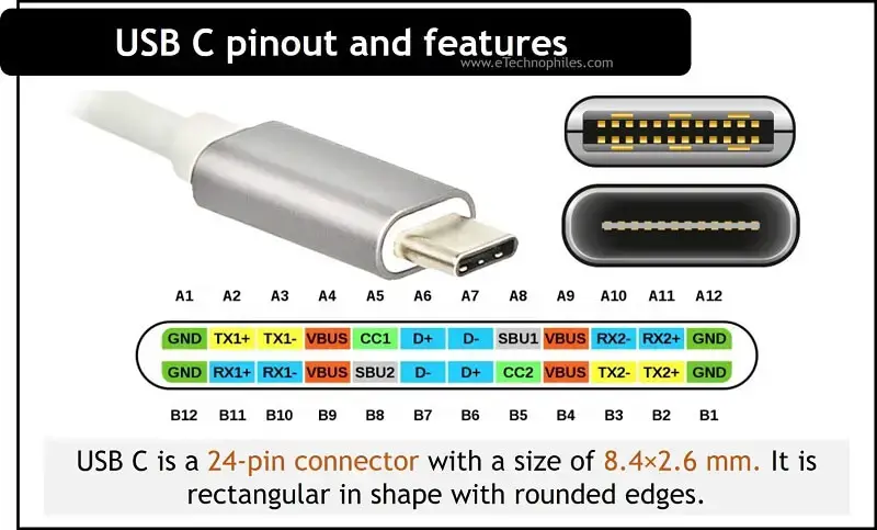
USB C is a 24-pin connector with a size of 8.4×2.6 mm . It is rectangular with rounded edges. The pinout diagram of the USB C connector is shown in the figure below.
Since USB C is rotationally symmetric, the pin allocation for the male and female connectors remains the same. The pinout description is listed in the table below.
| A1 | Ground | B12 | Ground |
| A2 | Superspeed differential pair 1, TX, positive | B11 | Superspeed differential pair 2, RX, positive |
| A3 | Superspeed differential pair 1, TX, negative | B10 | Superspeed differential pair 2, RX, negative |
| A4 | Bus power | B9 | Bus power |
| A5 | Configuration channel | B8 | Side Band Use (SBU) |
| A6 | Differential pair 1, positive | B7 | Differential pair 2, negative |
| A7 | Differential pair 1, negative | B6 | Differential pair 2, positive |
| A8 | Side Band Use (SBU) | B5 | Configuration channel |
| A9 | Bus power | B4 | Bus power |
| A10 | Superspeed differential pair 4, RX, negative | B3 | Superspeed differential pair 3, TX, negative |
| A11 | Superspeed differential pair 4, RX, positive | B2 | Superspeed differential pair 3, TX, positive |
| A12 | Ground | B1 | Ground |
Pin Description
Vbus and gnd pins.
One pair of GND pins are located at either end of the connector. VBUS pins allow power delivery with a voltage of up to 20V, but the default voltage of VBUS is 5V.
D+ and D- pins
D+ and D- pins are used from USB 2.0 standards for high-speed data transmission. There are two pairs of D+ and D- pins which are located at the center of the connector.
TX and RX pins
CC stands for channel configuration. The single pair of channel configuration pins handles functions such as plug orientation detection, current advertisement, cable attachment, and removal detection and also manages the communication between Power Delivery and Alternate Mode.
The SBU pair is used at low-speed signal paths while working in Alternate Mode.
The three standard wires that a USB-C cable consists are: 1. VBUS (Voltage Bus) : This wire carries the power supply. 2. D+ and D- (Data Positive and Data Negative) : These wires are used for data transmission. 3. GND (Ground) : This wire serves as the reference voltage and completes the circuit.
Leave a Comment Cancel reply


USB C Pinout Guide and Features
USB-C, or USB Type-C connector, is a 24-pin connector (not a protocol) that supersedes previous USB connectors and can carry audio, video and other data, e.g., to drive multiple displays, to store a backup to an external drive. It is a versatile and widely adopted connector standard that has become increasingly common in modern devices.
USB-C Pinout Definition:
USB C pinout diagram attempts to be reversible and has 24 pins. The USB-C connector has a pinout that defines the purpose and function of each pin within the connector. The USB Type C pinout specification outlines the pin configuration, and it includes multiple pins for various functions such as power delivery, data transfer, and alternate modes. Here is a brief overview of the USB-C pinout

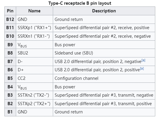
Type-C Receptacle
While the USB-C receptacle features 24 pins, not all need to be utilized. Simple devices like microcontrollers and low-power sensors can tap into GND and VBUS for power. By setting up resistors on the CC lines and detecting capabilities at the host, power delivery of 1500mA and 3000mA can be requested.
The USB-C plug is the connector that mates with the USB-C receptacle, creating a standardized interface for a wide range of electronic devices. The USB Type-C plug has a symmetrical design, allowing for reversible connections, and it features a specific pinout to define the function of each pin. Here’s an introduction to the USB-C plug pinout:
Vbus (Voltage Bus) : Pins A1 and B1 deliver power, accommodating charging and device powering with a potential voltage of up to 20V through Power Delivery (PD) negotiation. The VBUS and GND pins are power and the return paths for the signals. The default VBUS voltage is 5 V but the standard allows the devices to negotiate and choose a VBUS voltage other than the default value. The Power Delivery allows VBUS to have a voltage up to 48 V. The maximum current could be also raised up to 5 A. Hence, the USB Type-C could deliver a maximum power of 240 W.
D+ and D- (Data Lines) : Pins A6 and A7, and B6 and B7, ensure high-speed data transfer, supporting various USB standards like USB 2.0, USB 3.0, and USB 3.1 Gen 2.
CC (Configuration Channel) : Pins A5 and B5 facilitate communication between devices, negotiating power requirements, roles (source or sink), and configuration details.
SBU (Sideband Use) : Pins A2 and B2 serve for sideband signals, enabling Alternate Mode signaling for non-USB functions like DisplayPort or HDMI.
ID (Identity) : Pins A4 and B4 detect cable plug orientation and aid in accessory identification, determining whether a device acts as a power source or sink.
GND (Ground) : Pins A3 and B3 provide the necessary ground reference for power and data lines.
It’s important to note that the pin numbering is specific to the USB Type-C plug, and the same pinout is applicable to both ends of a USB-C cable. Additionally, when connecting devices, the communication between the CC pins is crucial for proper Power Delivery negotiation and role detection (whether a device is a power source or power sink).
UFP, DFP, or DRP: Understanding Port Roles
When two devices connect via USB, one assumes the role of a host with a downstream-facing port (DFP), while the other becomes a peripheral device with an upstream-facing port (UFP). Certain products, like mobile phones, can adapt to either role depending on the connected equipment. Creating a host device, which serves as a power source for other devices, involves implementing a Downstream Facing Port (DFP), typical in hubs or PCs. Conversely, developing a device such as a microcontroller, light source, or motor, which requires power, entails incorporating an Upstream Facing Port (UFP). Devices capable of assuming both roles are known as Dual Role Ports (DRP).
Detecting a Connection: The Simplicity of Voltage Measurement
Detecting a connection is straightforward with USB-C. By measuring the voltage on CC1 and CC2 pins, one can determine cable connection, orientation, and the type of connected device—whether it’s a host or a peripheral.
USB Power Delivery (PD): A New Era in Charging
Modern computers equipped with USB-C for charging can leverage Power Delivery (PD) to transfer up to 5A at 48V, providing a staggering 240W of power. While early PD implementations posed challenges, advancements in second-generation ICs are making PD support more accessible over time.
Alternate Modes: Beyond USB
USB-C isn’t confined to USB protocols alone. With alternate modes, it can replace HDMI and Thunderbolt cables, negotiating capabilities over the 24-pin cable for diverse functionalities. This requires circuitry for capabilities detection and line switching.
The Future of USB-C
USB-C is the future of connectivity. Its versatility, power delivery capabilities, and alternate modes make it the ideal solution for a wide range of devices. As the technology continues to evolve, we can expect even more features and functionality to be packed into this tiny connector.
Related Products

USB C to USB C Cable

100W Type C to Type C cable

Right Angle USB C Cable
40Gbps USB 4 Cable

USB C 3.2 Extension Cable
TYPE C OTG Cable
Eco friendly USB C Cable

2 in 1 USB C Cable
Wandkey is a MFI certified cable and charger manufacturer, supports OEM/ODM service , printing logo, customized packaging, color, length, mould etc . Welcome to contact us get the quotation and samples for the test.
Any questions feel free to contact us, we would be happy to solve your issues
Related Topics
USB C Connector Introduction
E-Mark Chip Introduction
Overview Of The Various Versions Of USB
How to Choose Fast Charging Cable for Your Phone
Do You Know USB C Cable (1)
How do I choose a USB-C cable?
Differences between USB 3.0 3.1 and 3.2
Test on USB C to USB C 3.1 Cable
Test on Right Angle USB C to USB C Cable
2022 Latest MFi Authorized Manufacturers list
Differences of Lightning Connector
How to check MFI Certification
How to get MFI Certification for Your Brand?
Why does the MFI Certified Lightning Cable so expensive?
MFI Product Packaging Requirement?
What’s the MFI Certification
Disassemble MFI Lightning Cable
iPhone 14 Pro may use USB C Charging Port
How the logo is printed?
How do we guarantee the quality?
What is Silk Screen Printing
How to identify counterfeit or uncertified Lightning connector accessories
What Plugs are Used in Different Countries
Leave a message
Related posts, 2024 latest mfi authorized manufacturers list, magsafe 3 vs magsafe 2, leave a comment cancel reply.
Your email address will not be published. Required fields are marked *
Save my name, email, and website in this browser for the next time I comment.

Get Quotation
Questions? Leave us a message, and our professional team get back to you shortly!
Stack Exchange Network
Stack Exchange network consists of 183 Q&A communities including Stack Overflow , the largest, most trusted online community for developers to learn, share their knowledge, and build their careers.
Q&A for work
Connect and share knowledge within a single location that is structured and easy to search.
Which pins from USB A goes to USB C in USB cables?
USB A 3.1 has in total 9 pins.
USB C 3.1 has in total 24 pins.
So how are cables like USB A to USB C built? Which of the 9 pins from USB A goes to the equivalent 9 pints in USB C?
USB A 3.1 also supports 10gbps, how is this possible with fewer pins than USB C 3.1?
Like USB 3.0, USB 3.1 uses one legacy USB 2.0 differential pair, and two SuperSpeed differential pairs (for a total of 6 pins), plus pins for power and ground. Wikipedia has the pinout details .
USB C for USB 3.0/3.1 was made to work no matter which way you plug it in, so it uses roughly half the available pins, plus two pins to select which ones. Wikipedia as the USB 3.0/3.1/3.2 mode assignments , as well as the pinout .
From that, it should become clear which pins are connected to which, which play a special role, and why not all USB C pins are used.
The difference in speed between USB 3.1 and USB 3.0 is because USB 3.1 allows an additional encoding scheme over the same two SuperSpeed pairs, which increases the signal rate. Again Wikipedia has details .
And you didn't ask, but USB 3.2 can also use all four differential SuperSpeed pairs of USB C connectors over an USB C cable, which is why it can achieve greater throughput using such a cable. Again Wikipedia has details .
- You beat me to it. So I'll just add a couple of points. In addition to extra pins for reversibility, USB C has some other intended uses, and additional pins for those uses. Not all of the pins get used for each application. Also, USB C is a smart connector with an embedded chip. So you can't create a simple A to C cable by just connecting the right pins, at least if the C connector is going to function as intended. – fixer1234 Commented Jan 9, 2019 at 11:56
- You might clarify if you mean USB 3.1 Gen 1 or USB 3.1 Gen 2 when you refer to "USB 3", "USB 3.1". – Ramhound Commented Jan 9, 2019 at 12:50
You must log in to answer this question.
Not the answer you're looking for browse other questions tagged usb-3 ..
- Featured on Meta
- We spent a sprint addressing your requests — here’s how it went
- Upcoming initiatives on Stack Overflow and across the Stack Exchange network...
Hot Network Questions
- Mathematical Induction over two numbers
- Definability of acyclic graphs
- Was I wrongfully denied boarding for a flight where the airliner lands to a gate that doesn't directly connect to the international part the airport?
- Why seperating a sphere gives different shades?
- \IfBlankF in \NewDocumentCommand removes content leading up to argument
- Citation hunting: Floer on spectral sequences
- Is it possible to have multiple versions of MacOS on the same laptop at the same time?
- 8x8 grid with no unmarked L-pentomino
- What methods can quickly determine the coefficient of determination of the data?
- Why can't CVP be trivially reduced to SVP by shifting?
- How can I remove rust stains from outdoor vinyl flooring?
- Is it an option for the ls utility specified in POSIX.1-2017?
- Is it possible to understand in simple terms what a Symplectic Structure is?
- Why does Google Maps only rotate 90º but not 180º when I rotate my iPhone?
- Installation error (MySQL)
- How can one count how many pixels a GIF image has via command line?
- How are Boggarts created?
- Has the Journal of Fluid Mechanics really published more than 800 volumes?
- Alternatives to iterrow loops in python pandas dataframes
- Is a "single" cpu safer than multiple cores?
- Coping with consequences of a dog bite before buying a puppy
- Why bother with planetary battlefields?
- Is taping behind tile necessary when drywall seams are not easily accessible?
- Why do jet aircraft need chocks when they have parking brakes?
- Browse CAD Models
- Virtual Librarian Service
- Reference Designs
- How We Help Manufacturers
- Become A Partner
- CAD Hosting and Creation
- Customized Development Solutions
- CAD Vendors
- Semiconductor Insights
- Terminology Guide
- Video Library
- Electronic Components Guide
- Embedded System Design

Understanding USB-C Pinout Requirements
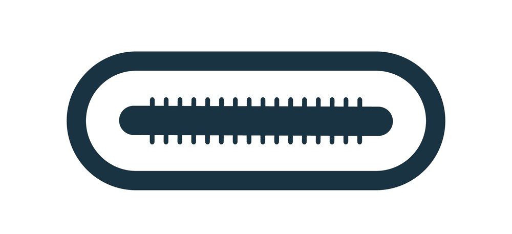
The USB-C pinout accounts for its ability to fulfill a wide swath of power and data roles.
A quarter-century ago, USB burst onto the scene as the grand unification of device peripherals in the computer landscape. Most people no longer had to worry about niche protocols and connectors for various interfacing devices. Within the last decade, USB continued its march as the primary interface for many device interconnections. It has recently been adopted as the standard for cell phone chargers in the EU. To say USB has been anything less than transformative in the peripheral space is an understatement. It is ubiquitous with nearly every electronic device due to its wide range of features and overall prevalence.
Designing hardware or software with USB in mind is a requirement in today’s layout world, and the key to understanding the latest USB connector system is the physical package. USB-C pinout is impressive at first blush due to its mating reversibility, but look underneath, and the staggering ability of the system reveals itself.
The Basics of USB-C Pinout
A vital distinction for USB-C: it refers to the design of the connector and is itself unrelated to the transfer specification. Since form follows function, USB-C is thus far the first and only connector that supports USB4. As visible from its pinout, the receptacle/plug interface is reversible:
|
|
|
|
|
|
|
|
|
|
|
|
|
|
|
| GND | TX1+ | TX1- | VBUS | CC1 | D1+ | D1- | SBU1 | VBUS | RX2- | RX2+ | GND |
| GND | RX1+ | RX1- | VBUS | SBU2 | D2- | D2+ | CC2 | VBUS | TX2- | TX2+ | GND | |
|
|
|
|
|
|
|
|
|
|
|
|
|
|
The USB Type-C receptacle pinout viewed end-on. The plug pin designators are mirrored horizontally across the center pins alongside slight changes to the pinout.
A quick descriptor of each pin function, by name:
|
| Return plane |
|
| Positive high-speed differential pair lines |
|
| Negative high-speed differential pair lines |
|
| Power |
|
| Channel config |
|
| Positive USB 2.0 differential pair |
|
| Negative USB 2.0 differential pair |
|
| Sideband use |
|
| Negative high-speed differential pair lines |
|
| Positive high-speed differential pair lines |
Alternatively, the plug for USB-C pinout substitutes the channel config pin on B5 gets substituted for a VCONN pin to enable power delivery services. The B6 and B7 pins are also removed, and the second USB 2.0 differential data lines go unreplaced.
One of the most compelling features of USB-C is the number of operating modes available. Since it is comparatively more robust in pin count and functionality than older physical USB systems, it can handily cover depreciated protocols without needing an intermediate translation. This news is welcome for users interfacing with older devices and systems, but USB-C offers much more than compatibility with legacy standards. The gains in transfer speeds mean that newer, modern protocols can also be supported for audiovisual purposes with a single connector system.
USB Operating Modes: Power and Compatibility
A simple pinout configuration, USB 2.0 mode allows for transfer using the basic differential pair topology. While the protocol is supported by USB 2.0, the physical interface between USB-C and 2.0 requires an adapter due to the differing pin count and receptacle/plug mating. Care should be taken when using A/B to C adapters as A/B plug and C receptacle combinations are invalid and undefined by the USB Implementers Forum. A mismatched pull-up resistor can cause devices to draw more power above maximum ratings, resulting in damage to devices and a potential safety hazard.
One notable advantage of 2.0 is the simpler transfer technology allows for longer cable lengths. A USB-C cable without the Tx/Rx lines can be up to four times as long as cables that support the full scope of USB-C capabilities.
|
|
|
|
|
|
|
|
|
|
|
|
|
|
|
| GND | VBUS | D1+ | D1- | VBUS | GND | ||||||
| GND | VBUS | VBUS | GND | |||||||||
|
|
|
|
|
|
|
|
|
|
|
|
|
|
* : Only one USB 2.0 differential pair can be active at any one time in this mode. Because of the reversibility of USB-C, B6/7 could be utilized instead of A6/7.
USB 3.x topologies utilize one or both of the high-speed differential pairs to realize bitrates much greater than the standard data lines of USB 2.0. USB-C connectors were developed and introduced alongside USB 3.1. All 3.1 and later cables natively support USB-C, including the most recent USB4 standard. 3.1+ and later standards can also output additional current at 1.5/3A.
|
|
|
|
|
|
|
|
|
|
|
|
|
|
|
| GND | TX1+ | TX1- | VBUS | CC1 | VBUS | GND | |||||
| GND | RX1+ | RX1- | VBUS | VBUS | GND | |||||||
|
|
|
|
|
|
|
|
|
|
|
|
|
|
* : For single-lane mode, only the differential pairs closest to the active channel config pin will be in use. Double-lane mode utilizes channel config pins and the four Tx/Rx differential pairs.
† : The USB 2.0 differential pairs generally go unused in USB 3.x mode, but certain devices can operate simultaneously or use the USB 2.0 differential pairs as backup lines in case of a USB 3.x transmission failure.
USB Power Delivery
Power delivery can provide power far above most USB standards: 20V/5A with specialty cables (or 20V/3A as the default specification). The Power Delivery mode is compatible with any data protocol provided one of the two CC pins is available, allowing for simultaneous power and data transfer .
|
|
|
|
|
|
|
|
|
|
|
|
|
|
|
| GND | VBUS | CC1 | VBUS | GND | |||||||
| GND | VBUS | VBUS | GND | |||||||||
|
|
|
|
|
|
|
|
|
|
|
|
|
|
* : Only one of the channel config pins are utilized in Power Delivery mode, but once again the reversibility of the USB-C system requires either A5 or B5 (but not both) during operation.
Additional Functionality and Support for USB-C Connectors
Alternate mode.
USB-C provides many exciting features. Still, perhaps none is more valuable to layout designers than the ability to replace a variety of ports with USB-C through Alternate Mode partnerships. Theoretically, this greatly reduces the complexity of routing and conserves land pattern space, an extremely valuable solution for modern HDI designs.
Supported interfaces include:
- DisplayPort : Primarily functions as a packetized audiovisual format, though it can send other forms of data.
- Mobile High-Definition Link : An audiovisual standard established between portable devices and televisions, projectors, etc., to piggyback existing connectors to avoid the need for additional connectors in small devices.
- Thunderbolt : Similar to USB, it combines multiple serial data transfer protocols (PCIe and DisplayPort) and power all on one cable. The most recent Thunderbolt revisions have adopted USB-C as their connector system.
- HDMI : Analog format for transferring video and audio, with additional support for digital audio output.
|
|
|
|
|
|
|
|
|
|
|
|
|
|
|
| GND | TX1+ | TX1- | VBUS | CC1 | D1+ | D1- | SBU1 | VBUS | RX2- | RX2+ | GND |
| GND | RX1+ | RX1- | VBUS | SBU2 | VBUS | TX2- | TX2+ | GND | ||||
|
|
|
|
|
|
|
|
|
|
|
|
|
|
* : Alternate mode allows for USB 2.0 differential pair transfer. Like in USB 2.0 proper, only one pair can be active at a time.
Audio Adapter
USB-C can support audio output from an on-device ADC or one within the adapter. Similar to other modes, device charging is allowed while using Audio Adapter, but only at USB 2.0 levels (5V/500mA) as the channel config pins are in use.
|
|
|
|
|
|
|
|
|
|
|
|
|
|
|
| GND | VBUS | CC1 | R | L | MIC | VBUS | GND | ||||
| GND | VBUS | AGND | CC2 | VBUS | GND | |||||||
|
|
|
|
|
|
|
|
|
|
|
|
|
|
* : Audio Adapter mode places the audio channel on one of the two USB 2.0 differential pairs, dependent on the orientation of the receptacle.
Debug mode allows engineers to test accessories by pulling the CC pins, either both high or low. Once entered, Power Delivery mode can be set up and results in the pinout shown below. All digital circuits are disconnected in this configuration to analyze the signal pins of the seven differential pairs.
All digital circuits are disconnected in this configuration to analyze the signal pins of the seven differential pairs. Debugging can be performed on all 14 lines when Power Delivery is active. When Power Delivery is not in use, seven test signal lines are available instead (TS1=A2/B2, TS2 = A3/B3, etc.)
The key to unlocking the potential of the most recent USB connector system is understanding the USB-C pinout and what features each mode can support. As much as end users enjoy the flexibility of an all-inclusive connector, designers benefit even more from a streamlined approach in compact layouts. Given the importance of the connector to a wealth of device applications, ensuring the quality of its associated land pattern can be the difference between a PCB assembly and testing progressing smoothly or requiring rework or revision.
Ultra Librarian assists design teams by providing an online library of millions of component footprints for popular ECAD toolsets . With a host of verified land patterns, layout teams can place components worry-free and turn their efforts towards optimizing performance. If you’re looking for CAD models for common components or helpful design information like USB C pinout requirements, Ultra Librarian helps by compiling all your sourcing and CAD information in one place.
Working with Ultra Librarian sets up your team for success to ensure streamlined and error-free design, production, and sourcing. Register today for free .
The Ultra Librarian Team
Ultra Librarian offers the world’s largest PCB CAD library, putting cutting-edge materials at your fingertips so you can build better products faster—all for free.
Join Our Newsletter
Subscribe to our newsletter to receive the latest news, and important updates
Related Posts

Electronic Component Kitting: Being Efficient

Top Electronic Component Distributors
Part Details
Free Design Resources
Ultra Librarian is the worlds largest online – and always free – PCB CAD library. Build products better, faster, and more accurately with easy access to vendor-verified symbols, footprints, and 3D models. Register today to start searching the right components for your next design.
Recommended

LM317T Datasheet: Important Considerations and Design Options

Data-Driven Circuit Design

The Impact of SMT Components on PCB Assembly

New 3D Models Available on Ultra Librarian
Search our blog.
- Announcement
- Component Parameters & Applications
- ECAD/MCAD Workflow & Team Management
- Frank's Garage
- Partner Content
- PCB Design & Layouts
- PCB Footprints
- STEP Models & 3D Integrations
- Uncategorized
All Things USB 3.1 And USB Type-C: An Explainer
Over the last year or so, there have been many developments in the USB space, and although the official specifications haven't changed, we've consolidated and explained all the helpful information around USB 3.0, both versions of USB 3.1, and the USB Type-C connector.
When USB 3.1 became common knowledge last year (even though it was actually released in 2012), there was some confusion. USB 3.1 was gaining attention about when the USB Type-C connector first appeared, so it's easy to understand how the two would be conflated. However, they're not the same thing. One is a data transfer protocol, and one is a type of connector. Another way of thinking of it is that Type-C is the pipe, and USB is (one of) the things that can flow throug h the pipe.
There is further clarification needed around other aspects of USB 3.1 and USB Type-C, though. A year past our last article on the subject , we spoke at length with the USB Implementer's Forum (USB-IF) to craft a primer, if you will, about all things USB and Type-C.
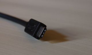
What's The Deal With USB 3.0, USB 3.1 Gen1, And USB 3.1 Gen2?
It's important to parse out the differences between USB 3.0, USB 3.1 Gen1 and USB 3.1 Gen2.
There are two types of USB 3.1: There's a Gen1 and a Gen2, and they offer different data transfer speeds. Both USB 3.0 and USB 3.1 Gen1 can transfer data at speeds up to 5.0 Gbps (8b/10b encoding), whereas USB 3.1 Gen2 can transfer data at speeds up to 10 Gbps (128b/132b encoding).
USB 3.0 and USB 3.1 Gen1 are actually the same thing -- almost. Simply put, USB 3.1 Gen1 is USB 3.0 plus all of the changes that have been made to USB 3.0 over the years. According to the USB-IF's documents, these changes include "added performance boosts to meet requirements for USB storage, display and docking applications," as well as USB 3.0 Engineering Change Notices (ECNs).
Stay On the Cutting Edge: Get the Tom's Hardware Newsletter
Get Tom's Hardware's best news and in-depth reviews, straight to your inbox.
"The USB 3.1 specification absorbed USB 3.0, meaning the terms USB 3.0 and USB 3.1 Gen 1 are synonymous," a USB-IF representative told Tom's Hardware. "By incorporating USB 3.0, we're reducing the number of documents a developer needs to reference (we're talking hundreds and hundreds of pages of technical documents that developers have to parse through) and including all relevant information to ensure products are properly developed to be backwards compatible (protocol-wise, not related to cables/connectors)."
The answer to the question that just popped into your head is no, there's no reason to market anything as "USB 3.0" at this point.
In order to clarify which is which and what is what, the USB-IF has turned to branding.
A Branding Issue
You may have never even seen an OEM specify "Gen1" or "Gen2" in marketing materials mentioning USB 3.1. Partially, this is because the USB-IF uses specific branding to clarify which USB 3.1 is which. USB 3.1 Rev1 (5 Gbps) is called "SuperSpeed USB," and USB 3.1 Rev2 (10 Gbps) is called "SuperSpeed USB 10 Gbps." Note that on the actual logos, these appear as "SuperSpeed" and "SuperSpeed+," respectively. (What's in a "+" sign? Double the data speed, that's what.)
This emphasis on branding has become of particular import in the wake of the launch of USB 3.1 and USB Type-C, as well as the rise of the USB Power Delivery spec. (USB PD is actually its own standard, apart from the data performance aspects of USB 2.0 and USB 3.1.) One could argue that the launches necessitated it, as not only are there multiple versions of USB 3.1 that require clarification, USB Type-C is a much more flexible connector (pun not intended) than older USB standards, and USB PD is another wildcard; in other words, the mere presence of a Type-C port on a device tells you little about what that particular port can do.
Instead, you should look for the branding in order to be able to tell what a port is capable of. Here it is in a handy table:
| USB | Alias | Logo (packaging) | Logo (on-product) |
|---|---|---|---|
| USB 3.1 Gen1 | SuperSpeed USB |
USB 3.1 Gen1 with USB Power Delivery (USB PD) N/AN/A
USB 3.1 Gen2 SuperSpeed USB 10 Gbps
USB 3.1 Gen2 with USB Power Delivery (USB PD) N/AN/A
USB 3.1 Gen 2 with DisplayPort over Type-C N/AN/A
USB 3.1 Gen 2 with DisplayPort over Type-C with USB PD N/AN/A
The colorful logos are used primarily on packaging, not on devices themselves. The SuperSpeed logo means 5 Gbps, and the SuperSpeed+ logo with the "10" means that it's USB 3.1 Gen 2 (10 Gbps).
The tridents and the battery icons are to be used primarily on devices themselves. The trident with no letters indicates USB 2.0. The trident with "SS" means SuperSpeed, and the trident with "SS" and a "10" means SuperSpeed+. When you see the above trident symbols encased in a battery icon, it means that those ports support Power Delivery.
Note that other indicators point to a port's support of other protocols -- Alternate Modes (or "Alt Modes") -- such as the "DP" that indicates "DisplayPort." Note here that Alt Modes are part of the Type-C specification, not part of USB 3.1, and they require USB PD to operate.
These logos and stamps can be used together, too. For example, if you see that a given port is stamped with a little "SS" before it, followed by a 10, enclosed in a battery, with a DisplayPort logo next to it, you're looking at a port capable of 10 Gb/s of data throughput with USB Power Delivery, and DisplayPort as an alternate mode.
Why Are There Multiple Versions Of USB 3.1?
A critical thinker would, at this point, be wondering why anyone thought it was a good idea to have two different "USB 3.1" generations in the market at the same time. It seems ludicrous -- but in fact, that terminology was never meant to be marketing terms at all. " [The two versions of USB 3.1] were not originally intended for consumers, which is why we promote the use of the certified brands SuperSpeed USB and SuperSpeed USB 10 Gbps," said a USB-IF representative. "The terms 'USB 3.1 Gen 1' and 'USB 3.1 Gen 2' are revision nomenclature terms used to identify the proper revision level of a specification and were not developed to be consumer-facing."
Essentially, what happened is that those terms simply "gained traction in the marketplace," and thus the group was stuck having to explain the terms along with its "SuperSpeed" branding.
USB Type-C Does More Than USB 3.1
As we mentioned, "USB Type-C" doesn't mean "USB 3.1." Although many -- possibly, most -- applications of USB Type-C will involve USB (one "Gen" or the other), the USB Type-C port design allows for additional features.
For starters, there is USB Power Delivery, which is a feature that allows devices to deliver up to 100 W of power through a USB port. Not every USB Type-C port will necessarily have this capability (remember, USB PD is its own spec), but it is an essential part of creating a single-cable solution that offers both data transfer and charging.
This is a powerful feature (if you'll excuse the pun), because it means that you could, for example, connect your laptop or phone to your monitor using a Type-C port and cable, which would send audio and video to a monitor, and the monitor could simultaneously charge your laptop (as long as all connected devices support USB PD).
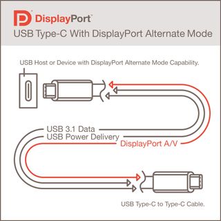
Additionally, USB Type-C can support DisplayPort as an Alternate Mode, as well as MHL and Thunderbolt 3 (with Intel's new Alpine Ridge controller). Theoretically, one could route just about any protocol through USB Type-C. Again, this will only be supported if the controller behind the port supports it. (You'll be able to tell whether a USB Type-C port supports DisplayPort by whether it has a little DisplayPort logo next to it. See how the branding is helping already?)
Not All Cables (Or Ports) Will Be Created Equal
One USB Type-C cable won't be identical to another, which means consumers will have to be careful when buying one, paying close attention to a given cable's capabilities. Thunderbolt excluded, things are quite simple: Some cables will support USB Power Delivery, and others won't. Most cables will support no more than 65 W power delivery, while other, thicker cables can handle 100 W.
Further, be aware that just because a Type-C port on a given device (or a specific Type-C cable) offers extra capabilities doesn't mean the device connected to it has the same. For example, if a cable has a male Type-A port at one end with four terminals, it will work no faster than a USB 2.0 cable (480 Mb/s), even if the other end is a USB Type-C plug.
One helpful factoid is that any USB 3.1-labeled cable will support both generations of USB 3.1. Therefore, whether the host has a data rate of 5 Gbps or 10 Gbps doesn't matter -- the cable will support it. (You'll only get the lowest common denominator performance, though, at 5 Gbps.) Again, however, a USB 3.1 cable doesn't necessarily support USB PD -- there will be additional markings for that.
When you take Thunderbolt into the equation, things will get a little more complicated, though. There will be three kinds of cables that work for Thunderbolt: up to 2 m-long passive cables that are limited to a maximum of 20 Gbps (Thunderbolt 2 speeds); 2 m-long active cables up to 40 Gb/s; and active optical cables, which can push 40 Gbps up to 60 meters.
Just One Problem…
All of the above is helpful information -- we've explained the key differences in current USB technologies and outlined how to identify them -- but there's one lingering issue: The branding is optional.
It is true that in order to use the branding, a given product must be certified by the USB-IF, which was a smart move on the group's part. The USB-IF trademarked the logos and branding, and OEMs can use them for free -- once they're certified. Therefore, when you see that branding, you can rest assured that it has passed the USB-IF's hundreds of tests. But because the branding is optional, the absence of the logos and stamps does not necessarily mean that a product has not passed certification.
OEMs can simply decide not to clutter up their sexy product designs with USB information. That's all well and good, but it creates a problem for consumers who then cannot tell, at a glance, what a given USB port can or can't do. Without the branding information, you have to go check the detailed specification list, and even then, OEMs may not have bothered to add clarification to those materials, either.
With USB 3.1 and USB Type-C, the USB-IF is stirring things up a bit. Rather than simply outing a new data rate and updating the Type-A, Type-B, Mini, and Micro connectors to enable the new data rate, there is more going on, and it will benefit the industry when features such as Alternate Modes and Power Delivery see wider adoption.
The next step is that OEMs need to help consumers by using the USB-IF's branding. And consumers should demand it.
Seth Colaner is the News Director at Tom's Hardware. Follow him on Twitter @SethColaner . Follow us @tomshardware , on Facebook and on Google+ .
World's first Thunderbolt 5 cable launched, 120 Gbps and 240W charging for $23 — Cable Matters new cable available now
DisplayPort vs. HDMI: Which Is Better For Gaming?
Intel preps Lunar Lake-optimized adaptive sharpening filter for Linux deployment
- WyomingKnott Three comments First, I wonder when the first USB C Displayport video cards and monitors will come out - if ever. Second, while a universal connector is a great idea in theory, there's an advantage in having a DVI cable that will only connect video to video. People will inevitably try to connect incompatible things and be puzzled when they do not work. Third, I absolutely love the idea of USB Power Delivery, where the host, the device, and the cable negotiate the amount of power desired / possible. But I foresee many cheap cables that don't implement this properly, and possibly more non-standard standards like the one Apple created. There will be problems. Reply
Three comments First, I wonder when the first USB C Displayport video cards and monitors will come out - if ever. Second, while a universal connector is a great idea in theory, there's an advantage in having a DVI cable that will only connect video to video. People will inevitably try to connect incompatible things and be puzzled when they do not work. Third, I absolutely love the idea of USB Power Delivery, where the host, the device, and the cable negotiate the amount of power desired / possible. But I foresee many cheap cables that don't implement this properly, and possibly more non-standard standards like the one Apple created. There will be problems.
- 3ogdy Great article! WHAT A language redacted MESS! What a language redacted mess! Then there's the optional branding...like....What the language redacted ?!?! OK, we're fitting this board with 3.1 Gen 2 10Gbps Type-C that also has Power Delivery of up to 100W, but we ain't gon' mention it...'cuz...why would we, right? RIGHT? Who cares about all those details? Nobody, right? Dumb language redacted should be banned from creating standards, from causing the entire planet headaches and some need to pay with their lives for it. This is unacceptable. Yet, somebody gets paid to come up with this. There's definitely a special place in hell for these people. Hopefully in front of a camera so we can see them "enjoying themselves", them pieces of language redacted . Reply
- atheus Thanks for this article, although I must say I'm heavily displeased that I need an article like this to really understand that the term "USB 3.1" has become basically meaningless. It's pretty much too late, but it sounds to me like they should just give up on the term USB 3.1 and call it USB 3.2 already. Everybody is used to calling these standards by their version numbers, so suddenly expecting everyone to start saying "It's Super Speed 10 GEE BEE PEE ESSS" or "USB 3.1 Gen 2" is a brush with insanity. The logos aren't all that helpful either, since much of the time these features will be listed in product descriptions on amazon and newegg with unsatisfactory detail. At the end of the day I think what will actually happen is that nobody should use the term "USB 3.1" when they mean Gen 1. That's just confusing. It's fine if engineers use the term internally, but for marketing that's just asking for trouble. That seems to be the way the motherboard manufacturers are going anyway. Reply
- InvalidError It is ironic how USB started because Firewire's six wires cable (TX pair, RX pair and power pair) was considered "too complex and expensive" and now we have Type-C USB which has two high-speed pairs in each direction, the legacy pair for USB1/2, a few extra wires for miscellaneous signaling and yet another pair or two for options. Type-C is going to be lots of fun when you end up needing a dozen different Type-C cables because each supports different options. Reply
- 2Be_or_Not2Be I think the USB-IF should have required the logos on any device utilizing the Type-C connector, not just for product packaging. Usually people don't keep the package, but they obviously will have the device. That would be very helpful when later down the road, someone wants to help you troubleshoot why their USB port doesn't act the way they thought it would. Reply
- SteelCity1981 this whole article just exposed how dysfunctional usb 3.x standard are. so usb 3.1 gen1 is the same 5gb speed as usb 3.0 with added features. and usb 3.1 gen2 is everything usb 3.1 gen1 has but with 10gb speed instead. so now you have to look carefully when you buy usb 3.1 to make sure it has the + next to the superspeed for usb 3.1 gen2 and not just superspeed for usb 3.1 gen1. Reply
Great article! WHAT A FRUCKING MESS! What a f(r)ucking mess! Then there's the optional branding...like....What the fruck?!?! OK, we're fitting this board with 3.1 Gen 2 10Gbps Type-C that also has Power Delivery of up to 100W, but we ain't gon' mention it...'cuz...why would we, right? RIGHT? Who cares about all those details? Nobody, right? Dumb mothercrackers should be banned from creating standards, from causing the entire planet headaches and some need to pay with their lives for it. This is unacceptable. Yet, somebody gets paid to come up with this. There's definitely a special place in hell for these people. Hopefully in front of a camera so we can see them "enjoying themselves", them pieces of sheet.
- Eggz Very useful information! I have four questions that I hope you can answer. First, will there exist a Type-C cable that supports ALL the top features? For instance, the max data rate for cables under the spec is 40 Gbps, but that's only by using active optical cables. Does using light (viz. optical) preclude full 100 w power delivery? It would be great to know which features have compatibility issues. Second, what exactly does "alt mode" do to the other functionality? That is, would a monitor running a DisplayPort signal through a Type-C cable still be able to provide 10 Gbps of data throughput, or does the DisplayPort signal cut into that bandwidth? Would the answer change using a higher bandwidth cable? How does the throughput get channeled internally? People will need to know, for instance, whether connecting new USB devices could cause their graphics cards to switch down from a PCI-e x 16 link to an x 8 link. I'm assuming these throughput levels will require PCI-e because they exceed SATA, but correct me if I'm wrong. Last, will there be an easy empirical way see which type of USB connection you are actually obtaining despite lack of labeling or technical specifications? For instance, Task Manager will tell you the link speed of your network connection if you don't know it (e.g. 100 Mbps, 1 Gbps, etc.). Even though you have a 1 Gbps NIC, you might run at 100 Mbps because the router or sever is using 100 Mbpg rather than 1 Gbps. In the same way, the weakest link theory for USB link speed negotiation will yield various actually connections, despite specs of individual components. Are consumers going to be able to just check like this for new USB standards using something like Device Manager or Task Manager? Reply
- targetdrone A single connector sounds awesome on theory until the reality that is Apple or it's wannabe cousin Samsung take it upon themselves to mess things up with a new proprietary connector or out of spec Type C connectors with the wrong number of pins. Reply
- View All 35 Comments
Most Popular

USB Type-C® Cable and Connector Specification
Usb type-c ® cable and connector specification.
With the continued success of the USB interface, there exists a need to adapt USB technology to serve newer computing platforms and devices as they trend toward smaller, thinner and lighter form-factors. Many of these newer platforms and devices are reaching a point where existing USB receptacles and plugs are inhibiting innovation, especially given the relatively large size and internal volume constraints of the Standard-A and Standard-B versions of USB connectors. Additionally, as platform usage models have evolved, usability and robustness requirements have advanced and the existing set of USB connectors were not originally designed for some of these newer requirements. This specification is to establish a new USB connector ecosystem that addresses the evolving needs of platforms and devices while retaining all of the functional benefits of USB that form the basis for this most popular of computing device interconnects.
LIMITED COPYRIGHT LICENSE
The USB 3.0 Promoters grant a conditional copyright license under the copyrights embodied in the USB Type-C ® Cable and Connector Specification to use and reproduce the Specification for the sole purpose of, and solely to the extent necessary for, evaluating whether to implement the Specification in products that would comply with the specification. Without limiting the foregoing, use of the Specification for the purpose of filing or modifying any patent application to target the Specification or USB compliant products is not authorized. Except for this express copyright license, no other rights or licenses are granted, including without limitation any patent licenses. In order to obtain any additional intellectual property licenses or licensing commitments associated with the Specification a party must execute the USB 3.0 Adopters Agreement. NOTE: By using the Specification, you accept these license terms on your own behalf and, in the case where you are doing this as an employee, on behalf of your employer.
USB Type-C ® Key Messages
- Slim and sleek connector tailored to fit mobile device product designs, yet robust enough for laptops and tablets
- Features reversible plug orientation and cable direction
- Supports scalable power and performance to future-proof your solution
USB Type-C ® and USB-C ® are registered trademarks of USB Implementers Forum.
Usb type-c ® compliance program.
The USB Type-C ® Specification can be found in the Document Library . USB Type-C ® testing is now available. For more information about USB Type-C ® testing please visit the USB Type-C Compliance Area . Information on how to register your product for testing can be found here .
In addition to passing USB-IF compliance testing and inclusion of its USB Type-C ® products on the Integrators List , companies wishing to use the certified USB logos must have a current USB-IF Trademark License Agreement on file. All implementation examples and reference designs contained within this Specification are included as part of the limited patent license for those companies that execute the USB 3.0 Adopters Agreement.
USB Type-C ® Language, Product and Packaging Guidelines
The USB Type-C ® Cable and Connector Language and Packaging Usage Guidelines are available for download here .

IMAGES
VIDEO
COMMENTS
USB type-c details. Developed at roughly the same time as the USB 3.1 specification, but distinct from it, the USB Type-C Specification 1.0 defines a new small reversible-plug connector for USB devices. The Type-C plug connects to both hosts and devices, replacing various Type-B and Type-A connectors and cables with a standard meant to be future-proof, similar to Apple Lightning and Thunderbolt.
The USB Type-C has interesting features. It supports a blazing fast data transfer speed of up to 10 Gb/s and high power flow of up to 100 W. These along with a flippable connector can make the USB Type-C a truly universal standard for the modern devices. To see a complete list of my articles, please visit this page.
USB TYPE-C Connector. USB TYPE-C is a new port designed for high speed data exchange and high power deliver capability. The first thing to realize is that USB TYPE-C is not a new USB standard like USB1.0, USB2.0, USB3.0, and USB3.1. Those are protocols defining speed and other features, whereas USB TYPE-C is all about physical connection.
The USB Type C pinout consists of 24 pins, each serving a specific purpose. These pins are organized into four groups: power pins, USB 2.0 data pins, USB 3.1 data pins, and configuration pins. Power Pins: Pins 1 and 4 are used for power delivery. Pin 1 is designated as Vbus, which carries power from the source (e.g., a charger) to the device.
USB Type-C is 10 Gbit/s and reversible (similar to Apple's Lightning), with symmetrical 24 pins so the connector will attach to the receptacle on the first try. The additional pins permit support of data protocols such as DisplayPort 1.3, PCI Express, and Base-t Ethernet using Type C cables. Figure 1 shows the pinout diagram of USB Type-C cable.
Bž >æÜ|I%·ðÜÎ7ð[‚ &ã¨rY µÌt vU µMŒÎ>ô6÷ˆ²OR8"ìù Ïy ‡¸ ¿½ YØùq2 Ë¢ÈÒ Áïã%à¶uYÓŒ˜y Rhç7ð[ÏO {oÈ:®©|› ‡A"6ÆD:·0 (bt8ÄäÔMCÏmÂ@ÓdõýwÐæ áå}Óq€—U´?ìYk a…¾c ÷ ŽçŸà7 ÛA C ëæWô-1ˆQ) OW E ÐÛ }Ååì¡[*á: nboM$ÒßiFe"µ3Ûd¦qq±ƒ(X€ åW¤ ;ñ 94«€ îß ...
USB type-C cable. Full-featured USB-C cables that implement USB 3.1 Gen 2 can handle up to 10 Gbit/s data rate at full duplex. They are marked with a SuperSpeed+ (SuperSpeed 10 Gbit/s) logo. There are also USB-C cables which can carry only USB 2.0 with up to 480 Mbit/s data rate . All USB-C cables must be able to carry a minimum of 3 A current ...
USB-C supports USB 3.1 and Thunderbolt 3 protocols, offering significantly faster data transfer rates compared to previous USB versions. With USB 3.1, data transfer speeds of up to 10 Gbps can be achieved, enabling quick and efficient file transfers. Power Delivery: USB-C supports power delivery up to 100W, allowing devices to charge rapidly.
24. Table 1: USB data transfer modes. USB 3.1/Gen 2 is essentially USB 3.0 with double the speed, to 10 Gbit/s. It is full duplex and not reversible, so the connector and receptacle has to be aligned in the correct orientation to be inserted. It has a total capacitance of 0.1 ~ 0.5 pF. USB Type-C is 10 Gbit/s and reversible (similar to Apple ...
USB C Pinout. USB C is a 24-pin connector with a size of 8.4×2.6 mm. It is rectangular with rounded edges. The pinout diagram of the USB C connector is shown in the figure below. Since USB C is rotationally symmetric, the pin allocation for the male and female connectors remains the same. The pinout description is listed in the table below. Pin.
By wandkey / 01/24/2024. USB-C, or USB Type-C connector, is a 24-pin connector (not a protocol) that supersedes previous USB connectors and can carry audio, video and other data, e.g., to drive multiple displays, to store a backup to an external drive. It is a versatile and widely adopted connector standard that has become increasingly common ...
A close look at the USB Type-C orientation-independent connector with a 24-pin signal plan through which it can deliver up to 10 Gbit/s, draw or supply up to 100 W, and cater to alternate high-speed signaling protocols. The USB Type-C connector is set to become universally applied due to its sleek design and robustness, its reversible plug orientation and cable direction, and of course its ...
Like USB 3.0, USB 3.1 uses one legacy USB 2.0 differential pair, and two SuperSpeed differential pairs (for a total of 6 pins), plus pins for power and ground. Wikipedia has the pinout details. USB C for USB 3.0/3.1 was made to work no matter which way you plug it in, so it uses roughly half the available pins, plus two pins to select which ...
The USB Type-C and Power Delivery specifications allow platforms equipped with USB Type-C ports to negotiate power levels up to 3 A at 5 V, 9 V and 15 V, and up to 5 A at 20 V, for a maximum 100 W power delivery. Besides power negotiation, the specifications introduce Alternate Modes so USB Type-C hosts and devices can add functionality like ...
Understanding USB-C Pinout Requirements. June 22, 2023. in Component Parameters & Applications, PCB Design & Layouts. 75 min read. The USB-C pinout accounts for its ability to fulfill a wide swath of power and data roles. A quarter-century ago, USB burst onto the scene as the grand unification of device peripherals in the computer landscape.
USB 3.1 Gen 2 with DisplayPort over Type-C with USB PD N/AN/A. The colorful logos are used primarily on packaging, not on devices themselves. The SuperSpeed logo means 5 Gbps, and the SuperSpeed+ ...
For the higher-speed USB 3.1 Gen 2, the PI5USB31213 provides the same functionality. The availability of both legacy 3.x and new devices will help ease a designer's transition to using the USB Type-C format. USB Type-C brings USB connectivity right up to date with a modern, compact, and reversible connector format.
USB-C plug USB-C (SuperSpeed USB 5Gbps) receptacle on an MSI laptop. USB-C, or USB Type-C, is a 24-pin connector (not a protocol) that supersedes previous USB connectors and can carry audio, video and other data, e.g., to drive multiple displays or to store a backup to an external drive. It can also provide and receive power, such as powering a laptop or a mobile phone.
For more information about USB Type-C ® testing please visit the USB Type-C Compliance Area. Information on how to register your product for testing can be found here. In addition to passing USB-IF compliance testing and inclusion of its USB Type-C ® products on the Integrators List, companies wishing to use the certified USB logos must have ...