The Defense Acquisition Encyclopedia

Acquisition Process
The Preliminary Design Review (PDR) is a technical assessment that establishes the Allocated Baseline of a system to ensure a system is operationally effective. A PDR is conducted before the start of detailed design work and is the first opportunity for the Government to observe the Contractor’s hardware and software design closely. This review assesses the allocated design documented in subsystem product specifications for each configuration item in the system. It ensures that each function in the Functional Baseline has been allocated to one or more system configuration items. A PDR is required by statute for all Major Defense Acquisition Programs (MDAPs)
Definition: The Preliminary Design Review (PDR) is a review conducted to evaluate the progress, technical adequacy, and risk resolution of the selected design approach for one or more configuration items; to determine each design’s compatibility with the requirements for the configuration item; to evaluate the degree of definition and assess the technical risk associated with the selected manufacturing methods and processes; to establish the existence and compatibility of the physical and functional interfaces among the configuration items and other items of equipment, facilities, software and personnel; and, as applicable, to evaluate the preliminary operational and support documents. – ISO/IEC/IEEE. 2009. Systems and Software Engineering – System and Software Engineering Vocabulary (SEVocab) .
Purpose of the Preliminary Design Review (PDR)
The PDR establishes the allocated baseline (hardware, software, human/support systems) and underlying architectures to ensure that the system under review has a reasonable expectation of satisfying the requirements within the currently allocated budget and schedule.
Fact Sheet: Preliminary Design Review (PDR) Fact Sheet
When to conduct a preliminary design review (pdr) [1].
A Preliminary Design Review (PDR) should be conducted when the Program Manager believes the system is ready for the following.
- The PDR is performed during the Technology Maturation & Risk Reduction (TMRR) Phas e before Milestone B , when the System Developer has initially baselined the high-level system architectural design.
- The PDR should be conducted when the allocated baseline has been achieved, allowing the detailed design of hardware and software CIs to proceed. A rule of thumb is that 10 to 25 percent of product drawings and associated instructions should be complete and that 100 percent of all safety‐critical component (Critical Safety Items and Critical Application Items) drawings are complete.
- The PDR should be conducted when all major design issues have been resolved, and work can begin on detailed design. The PDR should address and resolve critical, system‐wide issues before detailed design begins. [1]
- A PDR may be conducted incrementally for complex systems for each configuration item. These incremental reviews lead to an overall system-level PDR. System-level performance is supported by compliance with Interface Control Documents but is not assured. Interface requirements make up each configuration item Allocated Specification.
Mandatory Preliminary Design Review (PDR)
For Major Defense Acquisition Programs (MDAP) programs, a PDR assessment is conducted and provided to the Milestone Decision Authority (MDA) . DASD(SE) conducts a PDR assessment for ACAT ID programs to inform the MDA of technical risks and the program’s readiness to proceed with detailed design. For ACAT IC programs, the Component Acquisition Executive conducts the PDR assessment. The timing of the review should consider the following:
- Unless excused, PDR is carried out for all programs before Milestone B and before the contract award for engineering and manufacturing development. The Milestone Decision Authority (MDA) is also required under 10 U.S.C. 2366b to certify all Major Defense Acquisition Programs (MDAPs) at Milestone B. A PDR must be conducted and evaluated for this certification unless it is waived for grounds of national security.
- The timing of PDR in relation to the Development Request for Proposal (RFP) Release Decision Point is at the discretion of the DoD Component. It should balance the expense of extending the activities of multiple sources or having a development gap with the necessity for more mature design information. Regardless of this connection, the PDR assessment is carried out before Milestone B to help the MDA choose to start the detailed design phase.
Successful Completion of the PDR
A successful PDR is predicated on determining that the subsystem requirements, preliminary subsystem design, results of peer reviews, and plans for development, testing, and evaluation form a satisfactory basis for proceeding into detailed design and test procedure development. A PDR should produce the following. [1]
- An established system allocated baseline,
- An updated risk assessment for the Engineering, Manufacturing, and Development (EMD) Phase ,
- An updated Cost Analysis Requirements Description (CARD) or CARD-like document based on the system-allocated baseline,
- An updated program schedule, including system and software critical path drivers and
- An approved Life-Cycle Sustainment Plan (LCSP) updating program sustainment development efforts and schedules.
- Validated the CDD operational and suitability requirements
- The design is affordable, producible, sustainable, and carries an acceptable level of risk.
Preliminary Design Review (PDR) Completed Allocated Baseline
The allocated baseline ( Configuration Baseline ) is the configuration items making up a system and how system function and performance requirements are allocated across lower-level configuration items (hence the term allocated baseline). The PDR defines the allocated baseline and is formally under configuration control and is finished when the following conditions are met.
- All system-level functional and interface requirements have been decomposed and allocated to the lowest level of the specification tree for all system elements.
- All external interfaces to the system, as addressed in the System Requirements Review, have been documented in interface control documents.
- All internal interfaces of the system (system element to system element) have been documented in interface control documents.
- Verification requirements to demonstrate achievement of all specified allocated performance characteristics have been documented.
- Design constraints have been captured and incorporated into the requirements and design.
Preliminary Design Review (PDR) Roles and Responsibilities
When thinking about the roles and responsibilities of the Program Manager (PM) and Systems Engineer, the following tasks and roles should be taken into account when conducting a PDR:
The following are some of the Program Manager’s duties:
- Approve, pay, and hire people for the system PDR as planned in the Systems Engineer Plan (SEP).
- Setting up the plan to CDR in the SE Management Plan (SEMP), Integrated Master Schedule (IMS), and Integrated Master Plan (IMP), which are all part of the deal.
- Make sure that the SEP includes experts in the field in each study.
- Control the configuration of the subset of the functional and assigned baselines the government controls. Hold Configuration Steering Board meetings when changes are needed.
The following are some of the things the Systems Engineer is responsible for:
- Creating and carrying out system PDR plans with clear, measurable review criteria carefully designed to meet program goals.
- Making sure that the PDR standards that have already been set have been met.
- Giving the industry a chance to participate in this PDR planning (where possible, pre-contract award is a best practice).
- Making sure that assessments and risks related to all design constraints and considerations (like reliability and maintainability, corrosion, and Environment, Safety, and Occupational Health (ESOH) factors) are done, written down, and given.
- Plans for risk, issue, and chance are being updated. Identifying, mitigating, and monitoring risks and problems; and identifying, analyzing, managing, and tracking opportunities.
Preliminary Design Review (PDR) Benefits
Conducting a PDR offers many benefits crucial to the successful development and management of Major Defense Acquisition Programs (MDAPs).
- The PDR is a pivotal step in establishing the technical basis for the Cost Analysis Requirements Description (CARD). By meticulously documenting assumptions and rationale, it provides a comprehensive foundation for an accurate cost estimate for the Acquisition Program Baseline (APB) . This, in turn, facilitates technically informed cost estimates, enabling more effective should-cost/will-cost management throughout the project’s lifecycle.
- The PDR helps define the technical requirements essential for the detailed design phase, EMD (Engineering and Manufacturing Development) contract specifications, and the Statement of Work (SOW) .
- The review process establishes a robust basis for quantifying risks and identifying opportunities, contributing to informed decision-making and risk mitigation strategies.
- The technical foundation laid during the PDR is instrumental in meeting the 10 USC 2366b certification requirements, a mandatory step for all MDAPs, ensuring adherence to regulatory standards, and bolstering the overall success of the program.
The Weapons System Acquisition Reform Act of 2009 directed the PDR to:
- PDRs before Milestone (MS) B is mandatory for all Major Defense Acquisition Programs (MDAP) and will be reflected in the Technology Development Strategy (TDS) to be approved by the MDA at MS A . Post-PDR assessments will be conducted in association with MS B preparations and will be formally considered by the Milestone Decision Authority (MDA) at the MS B certification review.
- The timing of PDRs for other than MDAPs will be approved by the DoD Component MDA when consistent with TDS or Acquisition Strategy objectives. When the PDR is conducted before MS B, a post-PDR assessment will be conducted in association with the MS B review and formally considered by the MDA at the MS B review. If the PDR is conducted after MS B, the MDA will conduct a post-PDR assessment at a time reflected in the approved acquisition strategy.
- PDR before MS B is now a statutory requirement for MDAPs. The post-PDR assessment will be conducted during the MS B review and prior to the section 2366b certification by the MDA per title 10, Unites States Code.
Difference Between Preliminary Design Review (PDR) and Critical Design (CDR) Review
A Preliminary Design Review (PDR) is conducted to ensure new technologies are mature enough to be integrated into a product subsystem to form its allocated baseline and is required by statute for all Major Defense Acquisition Programs (MDAPs) . A Critical Design Review (CDR) determines if a system can meet its stated performance requirements within cost, schedule, and risk. It’s an independent assessment that informs the Milestone Decision Authority (MDA) of the technical risks and the program’s readiness to proceed with fabrication, system integration, demonstration, and test.
AcqNotes Tutorial
- The Program Manager (PM) should conduct the PDR when all major design issues have been resolved, and work can begin on the detailed design. The PDR should address and resolve critical, system-wide issues.
- IEEE 5288.2 “Standard for Technical Reviews and Audits on Defense Programs” is the standard for technical reviews and audits to be performed throughout the acquisition life cycle for the US Department of Defense (DoD) and other defense agencies. This standard guides the DoD and contractor on what is required during an SRR
- The PDR should be conducted when the allocated baseline has been achieved, allowing the detailed design of hardware and software configuration items to proceed. A rule of thumb is that 10 percent to 25 percent of product drawings and associated instructions should be complete and that 100 percent of all safety-critical component (Critical Safety Items and Critical Application Items) drawings are complete.
AcqLinks and References:
- Defense Acquisition Guidebook
- [1] Preliminary Design Review (PDR) Fact Sheet
- Preliminary Design Review Checklist – Jan 2015
- PDR Risk Assessment Checklist – 18 April 2013
- NAVAIR Instruction 4355.19D – Systems Engineering Technical Review
- OSD Guide to Best Practices Using Engineering Standards – April 2017
Updated: 2/5/2024
Leave a Reply
You must be logged in to post a comment.

Preliminary Design Review Outline
Preliminary Design Review (PDR)
The purpose of the Preliminary Design Review (PDR) is to formalize all of the information regarding your project into something that anyone without prior knowledge would be able to understand what was being attempted. It will also help clear up any issues or misunderstandings between the customer and the team. This blog post provides information about what documentation is required and some examples of how to create them.
The PDR can be considered to be made up of two main sections, the project documentation and the project plan / schedule. The project documentation focuses on details about what the team will be designing and involves things such as the requirements, system block diagram, and software block diagram. The project plan / schedule outlines how the team plans to complete the project within the semester. You will be required to complete and present both for the PDR presentation.
Table of Contents
The objective of the Preliminary Design Documentation is to lay out the preliminary “technical” design of the project as defined by the Level 1 and 2 requirements, system design, and modeling. While the preliminary design needs to provide a clear description of the project, it is understood that the creation process follows the System Engineering Method and is therefore iterative by nature . You can consider this being a snapshot of the design process for future students to learn from if they continue working on the next generation of the robot.
Title Slide / Cover Page
This section of the presentation / document should contain the following:
- Name of project and current school term
- Team member names and respective division assignments
- Project related picture or illustration.
Program / Project
Objectives / mission profile.
The process begins with the identification of the problem to be solved, and/or product to be built as defined by the customer and codified by the Program Objective Statement. Although the Program Objective may be in the form of a requirement, it is typically a qualitative statement of what the customer wants. These “objectives” are not developed in isolation or at a fixed point in time but like all elements of the engineering method, evolve over the life of the project.
For example, after a system design is selected and the manufacturing element of the project comes to the fore, you may need to ask the customer about how easily the widget needs to be put together or taken apart for repair. The answer may require a redrafting of the program objectives, program requirements, system/subsystem requirements, and associated verification tests.
The Mission Profile documents how the product will be operated by the customer and is focused on the conceptual operation (ConOps). For many of our robots, the Mission Profile is defined by the course it will run on the day of the Final. This can also lead to additional requirements being generated as you find issues that were not considered.
Constraints
Present Constraints on the project imposed by The Robot Company and Project Stakeholders as defined in the “ Program Constraints ” section of the “Realistic Constraints and Engineering Standards” lecture. Catagories include: Project/Economic, Social and Ethical, Manufacturability, Environmental Health and Safety (EH&S) Standards, and Functional. Adapt material under these categories as applicable to your project.
For example, any 3DoT project will have to follow these “Functional” constraints. You may have a requirement that is similar, so change it to use the wording shown here.
All 3DoT robots shall incorporate the 3DoT v8 or later series of boards.
Software shall be written in the Arduino De facto Standard scripting language and/or using the GCC C++ programming language, which is implements the ISO C++ standard ( ISO/IEC 14882:1998 ) published in 1998, and the 2011 and 2014 revisions. Required exceptions to this standard can be found here .
All 3DoT robots shall be in compliance with the 3DoT Command and Telemetry Packet specification.
All 3DoT robots shall be controlled via Bluetooth 4.0 in compliance with the Bluetooth Special Interest Group (SIG) Standard (supersedes IEEE 802.15.1).
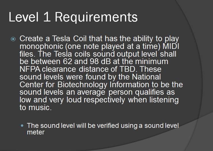
Requirements
Start by reviewing the following material.
- Requirement Types
- High Level Requirements (Level 1 Program/Project)
- Derived Requirements
From the mission objectives statement, Program and Project Requirements are written. Often the simple (only by appearance) process of defining a program requirement, will require rethinking program objectives and introduce new calculations that need to be performed, trade-off studies to be conducted, new models / prototypes that will need to be built, and experiments to be conducted. In other words each step in the engineering design process sends ripples both up and down the project.
- Each requirement should be numbered for later reference.
- While each requirement must be paired with one or more verification tests, this second step will be implemented in the next iteration of this document.
- Clearly indicate which level the requirement falls under. Make sure that the linkages for each level are apparent. Specifically, the level 1 requirements clearly show they were derived from the mission profile or project objectives. Level 2 requirements directly follow from Level 1 requirements.
You should indicate your initial thoughts on how to verify the requirement. This will help identify if you have worded the requirement properly.
Like the layers of requirements preceding them, each requirement level (program, project, system, subsystem), must be responsive to higher level requirement(s). They may never stand alone. To clarify, Level 2 requirements respond to Level 1 and Level 1 requirements respond to the project objectives / mission profile.
A single level 1 requirement will typically spawn multiple level 2 requirements; just as level 2 requirements can be traced to multiple level 1 requirements. In other words, there is not a 1:1 correspondence.
Design Innovation (As Applicable)
Once a first draft of the program/project requirements is done, the project team searches for creative design solutions (design ideas) for potential problems or issues that need to be addressed. This is where the creativity methods discussed in class can help.
This section is not required for problems or issues where the solution is dictated by the project objectives or mission profile. If the design solution has never been done by previous semesters, then this is needed in your presentation.
System Design
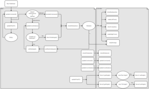
System block diagram.
Another aspect of the system design is the clear definition of the subsystems and the interfaces that exist between them. From an electrical engineering perspective, this definition is predicated by the System Block Diagram, followed by a description of the subsystems, their interfaces and requirements.
This diagram should clearly define all of the subsystems that make up your project and show how they interact. One additional detail that would be helpful is to show how the subsystems fit together. For example, many subsystems will physically be within the chassis of your robot. It would be useful to represent that and show the interconnections on the inside.
Do not overload the diagram with long paragraphs describing each subsystems function. Be prepared to explain this verbally during the presentation.
Example System Block Diagram from Tesla Roadster
The key thing here is to break down your project into its major parts and show how they are related. If it can be broken down further, make sure to present it in a way that makes sense.
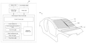
Interface Control Document (As Applicable)
When two or more projects are subsystems of a larger project, they will need to coordinate how those subsystems interact. That results in the interface control document (ICD), which explains how the different interfaces of each project should be defined to keep everything organized.
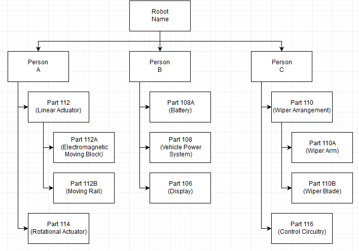
Product Breakdown Structure
The major subsystems comprising the system are defined in the Product Breakdown Structure (PBS). The WBS will be covered in the Project Plan / Schedule section of this post.
The important thing about this section is that a specific person is clearly associated with a product deliverable. It is based on the system block diagram and WBS. Everything shown in the PBS should be representative of the details from those documents. An example is shown below.
Subsystem Design
Software design.
This section includes any material that helps portray how the software will need to work. It can consist of program flowcharts, block diagrams, or any other visual aid to show how the final code will perform.
Application Customization
If your project needs to incorporate the Arxterra Control Panel or ArxRobot app in any way, you will need to show how it will be used and/or customized.
Firmware Customization
It also shows custom MCU Firmware that needs to be generated. As things are being planned out, you may use placeholder names for the functions needed as long as it is relevant (does not need an explanation for what the purpose is).
You should make use of the universal modeling language (UML) for these diagrams. This is shown below with examples taken from Pathfinder Generation #7’s PDR.
Program Flow during operation
The first diagram is showing how the functions will interact with each other and at what point in the program they will be called from. It helps show how the structure will be implemented.
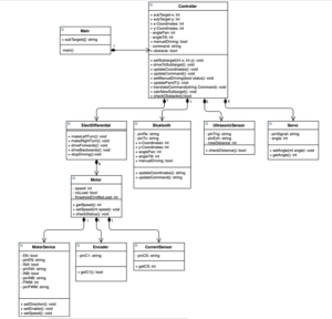
Function and Variable Descriptions
The second diagram is showing additional details about each function and the variables involved with each.
Electrical Design
For a microcontroller based design, the electronic interface definition begins with the Interface Matrix and is finally documented by detailed schematic(s). At this point, there should be a clear picture of what will be going onto the custom PCB shield that will be designed.
Interface Matrix (Optional)
As an option your project may provide an interface matrix for each microcontroller or printed circuit board (PCB) to indicate the different wires and their function on that board. Shown below is an example of how this should be done. While it may be tedious, you should indicate all available pins for the device and indicate when that resource has been taken.
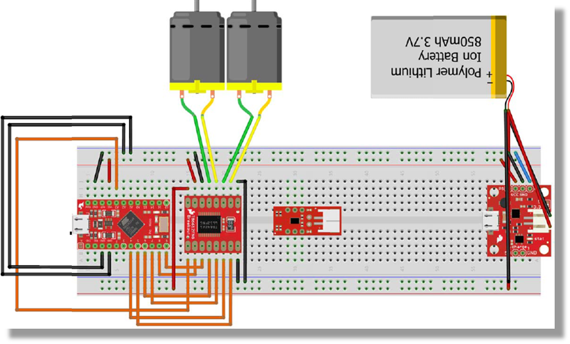
Electrical Breadboard
For the PDR it is sufficient to document the electronic design using a Fritzing diagram and/or photograph of the breadboarding done. This should lead to the custom PCB shield schematic created in EagleCAD, which may also be shown in the presentation (i.e., optional).
You can find additional information on how to make the Fritzing diagram here .
Mechanical Design
From a mechanical engineering perspective, the system design is predicated by a 3D mechanical rendering of the system with sub-assemblies clearly identified. This is typically done with an annotated exploded view of the system, followed by a description of the subsystems, their interfaces and requirements. Ideally, the best representation of the system will be from SolidWorks models but the complexity of the project may make it difficult. If you feel the model is lacking, include additional material only if they add to the presentation.
Do not show pictures of hand drawn sketches or Microsoft Paint drawings.
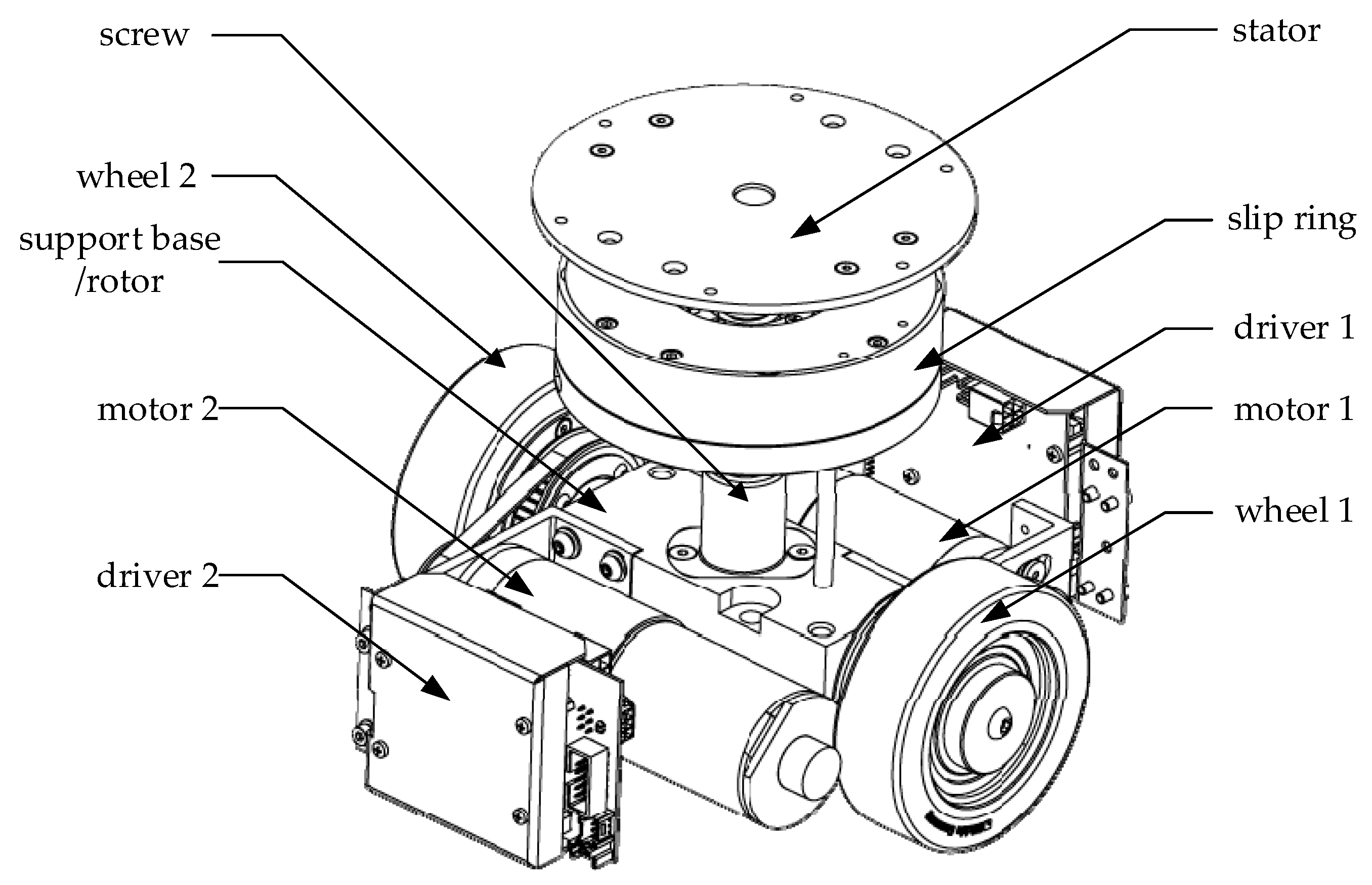
Source: A Master-Slave Separate Parallel Intelligent Mobile Robot Used for Autonomous Pallet Transportation
Project Planning
Work breakdown structure.
The WBS is a hierarchical breakdown of the work necessary to complete the project. (NASA System Engineering Handbook Section 4.3.2.1 Product Breakdown Structure).
Your WBS should be taken to a level such that tasks within each structural element are assigned to a single engineer. Specifically, organize all your tasks into groups in some hierarchical tree structure where each node (group) is the responsibility of only one engineer. Normally, the hierarchy will fall along Division/Section/Group lines.
Given that we are not following the matrix organization this semester, the WBS should be structured according to the project members and the work that they are responsible for. IE Person A is responsible for Task 1 (designing 3D model), Task 2 (Printing and assembling robot), etc. You can find more information about the WBS from the class lecture .
Design and Unique Task Descriptions
After a first pass through the Engineering Process, you should have a fairly complete set of Task Definitions. These definitions include a short description of each task that needs to be performed and its duration. Once these tasks are defined, the projects take them to the divisions where engineers are assigned to complete them across the division (see Work Breakdown Structure ). For example, if multiple projects need to know more about the characteristics of a servo, then only one engineer needs be assigned to gather information, define a test plan, and then conduct and document the test results.
Each member should develop the list of tasks that they will be focusing on in the coming weeks. A brief explanation of how they plan to approach it should be provided. For example, the E&C engineer is responsible for the custom PCB design and they may plan to breadboard the individual components that will go on the PCB to confirm how the wiring should be done before developing the schematic. It may take two weeks or more for breadboard testing, evaluations of the design, and revisions before being complete.
These tasks can include applicable sketches, back of the envelope, trade-off studies, models, etc.
Trade off studies must begin and end with requirements that are the key factors in making a choice. Trade-off studies must be quantitative.
Avoid words like: Typically small, Large Torque, Very accurate and precise, Highly efficient, Has reserve power and torque, more likely to malfunction if subjected to overload, precise positioning, stable, quick starting and stopping, small step distance, it’s possible to “skip” steps with high loads, draws maximum current constantly, low self-discharge, very high energy density, A little expensive, high shelf life. Provide exact values if possible from datasheets or calculations to allow for accurate comparisons.
The main focus of this section is to lay out what are the critical things each team member will be working on and how they may plan to do them.
Once that is covered, you should present the results from any experiments that you have performed. For example, any breadboarding or back of the envelope calculations that were performed should be discussed here.
Do not simply copy-paste material from previous generations of documents. Give proper credit for any work that you not responsible for.
Project Schedule
For the project schedule, create a timeline of the tasks that will need to be completed based on what was covered from the “Design and Unique Task Descriptions”. This can be done in Microsoft Excel or Google Spreadsheet and should indicate the description (from the previous section) and duration of each task. Make sure to also include the major milestones such as the V2 Demo, CDR (November 5th for both) and the final (December 12th). Limit to aproximatly twenty (20) tasks.
The following figure shows a simple seven (7) task “waterfall” schedule. Each task is represented by a blue box. Dependency between tasks is shown by a blue arrow. The two milestones described in the previous paragraph are also shown. The critical path is shown in green. While the completion times of blocks not on the critical path can slip (illustrated by dotted green lines), any slips in tasks on the critical path will result in the project not meeting one or more of the project milestones.
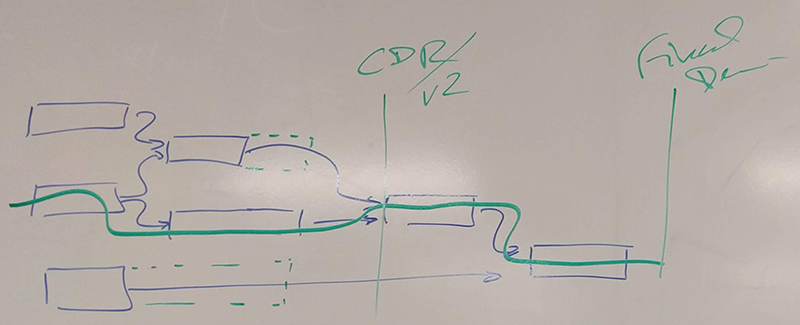
Simple Waterfall Diagram
The top level schedule provided in this section should be developed using Microsoft Project or Project Libre. The top level schedule should be built from (linked to) WBS modules. Each module should in turn be linked to system/subsystem level tasks. These tasks may include trade-off studies and modeling (including rapid prototyping) as described in the next section and defined in the Preliminary Design Document. This is because it will help show how the tasks are dependent on each other and keep track of progress being made. Ideally, you will be able to get to this point a bit later in the semester.
From Microsoft Project, create a table of tasks needed to implement the project at the System and Subsystem level as defined by your WBS. A time estimate with uncertainty should be attached to each task. These tasks should be in response to those tasks defined in the Preliminary Design Document.
If you have any other project management software that can generate this, feel free to use that as an alternative to Microsoft Project or Project Libre.
Burndown (Optional)
The purpose of the burndown diagram is to show the projects progress up to this point. Depending on how the project schedule is defined, it should give an estimation of how work should be progressing.
The percent of project completion is computed as follows. When a task is started, 50% of its weight is assigned as completed. When a task is completed, the remaining 50% is added to the score. Task completion must be approved by the president or the vice president. Proof of completion (blog post, documentation, etc) needs to be provided for each task before it can be considered finished. There are two approaches to how to define the burndown diagram.
Each task can be evaluated based on percentage completion or the number of hours it would take to finish.
For the first method, the total number of tasks needs to be considered. As each task is completed, you compare it to that total. I.E. 5 tasks are completed with another 4 that have started. That would correspond to 7 tasks (1 for each task done and 0.5 for each started) out of a total of 30. Therefore the total percentage done would be 23.33%.
For the second method, the total number of hours needs to be considered. As each task is completed, you compare it to that total. I.E. each task may vary for the number of hours needed. Assume the average is 4 hours for each task. For 5 tasks completed and 4 that have started, it would correspond to a total of 28 hours (4 for each completed task and 2 for each started task). If the total for the project is 84 hours, the total percentage would be 33.33%.
System Resource Reports (As Applicable)
Resource Reports (i.e., resource allocations), as they are applicable to the project, show how shared resources are allocated among the different subsystems. For example, power allocation/estimate for each subsystem module help to evaluate the total needed for the battery. Each resource should have a margin attached to it based on the uncertainty in the estimate . It should also show contingency, where contingency is defined as the project allocation minus the estimate and total margin .
One important consideration for these resource reports is that the project allocation for that resource needs to be justified or derived from a requirement. Often, this is arbitrary due to the characeristics of a student project. However, to be realistic, there is some form of a constraint that limits what is allowed. Therefore, the project allocation for each resource needs to be clearly defined as it shows how the design may run into problems with the choice of components and leads to the specifications of what is needed (operating voltage, etc).
For example, most projects will need a power resource report. This report would factor in the available power, typically the current rating of the RCR123A battery selected, and the operating time, typically a function of the mission profile.
This section is dedicated to the total mass of the project. Also in a tabulated format, it should contain the expected weight, measured weight, percent uncertainty, and margin for each respective resource being used in the project. Lastly, it should contain total expected weight, total margins, project allocation, and contingency.
This section shows the different power demands of the various components used. There are several ways to represent the power (watts, mA, or mAh), so make sure to pick one. Typically represented in a tabulated format, it should include an expected current drawn, measured current drawn, percent uncertainty, and margin for each resource consuming power (for the mA case). Lastly, it should contain total expected current, total margins, project allocation, and contingency clearly showing the power source selected will support the project.
Other Shared Resource Report(s) / Allocation
Any other resources tracked by the system engineer. For example, projects using the libraries 3D printer, should show how cost is minimized, based on library’s pricing algorithm.
A unique resource report for the Card Shuffler project would be related to their Mission Profile. For example, a time resource report is needed to indicate how much time each part of the process should take in order to shuffle and identify if any cards are missing.
Within the introduction of this section, please indicate the funding source for this project. This is a table containing a parts list of all items to be purchased in support of the project. Each line item should include a margin if the actual item to purchase has not been defined. It is important that the estimate be as comprehensive as possible. Please do not leave off the list items for which you are know you will need but currently have not identified a model number/source. For example if you know you are going to need a servo but am not sure about which one then research the cost of servos and use the mean cost as an estimate with an uncertainty that makes sense. Finally, at the end of the table add a margin. This is to cover any contingencies including broken parts, parts you forgot about, etc. This margin should decrease with time as the project becomes better defined. If there are any parts that you will be borrowing from the cabinets or previous generations, please indicate those as well on this list and consider their actual cost to be 0. Add a note that it is being provided from previous semesters.
PDR Grading Rubric
The PDR presentation will be graded, consistent with the outline of this document. Sections and material designated as “optional” and “as applicable” are not required.
Closing Thoughts
- Original work – what you have learned
- Do not show copied material without citation.
- Demonstration of the Engineering Method – From Objectives to Design
- Do Not Show Product Pages
- Copied Promotional Text
- Specification Without Linkage to a Requirement(s)
Preliminary Design Review
This purpose of this document is to help you prepare the Preliminary Design/Low-fidelity Review (PDR) oral presentation and written report. Most of the items listed are just suggestions, but others, as noted, are required. A large part of your task is to use the constrained time and alloted space to best convey the status of your project to your sponsor. You must seek and gain their approval to move to the next phase, Critical Design.
The overall goal of the PDR is to convince your stakeholders (in this case, your instructor acting as your project sponsor) that there is a problem worth solving and that your team will be able to create unique solution and value for the customer. At the end of the presentation, the sponsor should be motivated to move the project to the Critical Design phase.
Low-fidelity Virtual Prototype Assessment
The goal/outcome of the low-fidelity prototype is to provide design insight and intent, while assisting and improving the team's chances for success. It should
- Communicate the general size (footprint and volume) using approximate (and appropriate) dimensions,
- Communicate general fits, tolerances, material properties, etc.
- Communicate a preferred layout of subsystems and/or components
- Display general functionality
Students are encouraged to begin early using virtual tools like Inspire and traditional CAD to begin conceptualize the shape, topology, diemensions, etc of your proposed design. The virtual prototype should be refined/finished as accurately and completely as time and your resources allow. If you are in a face-to-face lab then you need to take your virtual low-fidelity prototype and by using cardboard, plastic, wood, etc. and with the help of glue, tape, brads, pins, etc. construct the components, sub-systesm and overall system that represents your team's physical low-fidelity prototype. A second outcome of this assignment is getting your team into the mode and consideration of team knowledge, resources, skills relating to all things virtual, i.e. CAD, CAE, CAM, CAT, etc and physical, i.e. primitive manufacturing processes.
Oral Presentation
20 minutes for presentation, 3 minutes for q&a.
Content (“What”)
- Explain the problem you are solving. Be sure to clearly identify a problem, not just a project that you are working on. (A problem causes people dissatisfaction at some level.)
- Explain the physics of the problem (requires 1st order mathematical models and simulations that show the physics of the problem).
- Explain what others have done to solve this problem. These are benchmarks. This includes other customers, product manufacturers, researchers, inventors (patents), competitors, etc. There will be different emphasis in these areas depending on the nature of the problem you are solving.
- Compare how you plan to position your solution with respect to the benchmarks.
- Define customers for the solution you propose, and define engineering requirements (quantifiable measures of performance; lower cost, faster speed, higher resolution etc.) that you will use to evaluate your design concepts. Select targets for your engineering requirements, and compare with benchmarks.
- Some are high risk (may not work) but high potential pay-back
- Some are low risk (probably will work) but don’t meet all the requirements
- From variety of sources (patents, functional decomposition, etc.)
- Show concept blending - Combine the best features from several concepts
- Tell what is innovative about each concept
- Technology readiness (risk assessment of “will it work?”)
- Simple, 1st cut performance calculations to show feasibility
- Show 1st and 2nd choice final concept with justification.
- More sketches, diagrams, schematic, pictures, charts, spreadsheets, etc. than words.
- More pictures, charts, spreadsheets, etc. than words.
- Formal CAD drawings are not necessary, but concept sketches (pictorial, orthographic, mechanical, electrical, etc.) must be clear.
- Organization/Roles
- What we Propose to Design.
- What we propose to Analyze.
- What we propose to Prototype.
- Appendix slides that deal with your most predicted questions.
- Showing other aspects of your problem definition
- Showing other aspects of you concept design
- Presenters are wearing appropriate attire, speak clearly, are confident and credible, and passionate about their project and product.
- The presentation is visually appealing, engaging, easy to follow, and easy to understand. Please don’t overfill a slide with too many texts and just read them off. Each slide has a well-defined & intuitive take-away that contributes to the overall message so that the full presentation communicates a clear and significant idea that energizes the sponsor to support the project.
Written Report
- The report is to be no more than 500 words; an Executive Summary. With the appropriate use and reference to well-chosen embedded figures, CAD models, electrical schematics, tables, diagrams, lists, etc. the body of the report will cover multiple pages. Points will be deducted for reports longer than 500 words. (Requirement)
- The report should be easy and quick for the sponsor to read. It should provide a summary of the most important team organization, problem definition, conceptual design, project management elements accomplished thus far on the project. For more in-depth discussion and/or background refer the reader to the appropriate appendix. Remember an Appendix provided but un-referenced in the body of the report should not be in the Appendix.
- It is written to the same audience (project sponsor) as the oral presentation and serves the following purposes:
- Provide a concise problem/project statement
- Target customers
- Unique value
- Unit costs to sales price and predictions
- Discuss how your efforts in Problem Definition and Conceptual Design have led to a successful down selection of the concept your team is taking forward into Detail Design and Analysis. Highlight the use of brainstorming, 1D & 2D analyses that led to initial size, shape, thickness, gaps, fits (allowance, clearance, tolerances, etc.), etc. for your products most significant parts and assemblies. Other results can be given in Appendices & .
- If controls and actuators are required, discuss the design of the control system providing appropriate schematics, calculations, component requirements, etc. Other results can be given in Appendices & .
- It reinforces the Oral Presentation and key takeaways. It does not introduce new materials or results, but points to appropriate appendices for the material supporting your statements.
- Requests approval to move to the next phase of the project.
- Report Name
- Project Name
- Submitted to: Sponsor Name (if no sponsor, list your professor)
- Submitted by: Team Names
- Introduction - describes the project and discloses the current project stage (state-of-affairs)
- Background - discusses how you arrived at the PD & CD stage
- Problem Definition - discusses the gathering and refinement of specifications and requirements for the project
- Conceptual Design - discusses how potential concepts were identified and evaluated
- Proposed Preliminary Design and Low-fidelity Prototype - discusses how you arrived at the best concept and show a dimensionally accurate but low-fidelity prototype
- Request to proceed to Detail Design.
- A: Team Members and Organization Structure
- C: Business Case and Project Budget
- D: Project Schedule, Network Diagrams, Work Breakdown Structures, etc.
- E: Risk Mitigation
- F: Sketches
- G: Mechanical CAD
- H: Mechanical CAE (FEA, CFD, motion path simulation, … depending on your project)
- I: Electronic Schematics
- J: Electronic Circuit Diagram/Wiring Diagram (if ready)
- K: Electronic CAE
- L: Flow Chart of Control/HMI Software/Operation and/or Skeleton Code (pseudo code)
- M: Manufacturing Drawings
- N: What was learned from low-fidelity prototype
- O: List of Standards Referenced/Used/Applied to this project
- P: ...other appendices as applicable
© 2016 Purdue University | An equal access/equal opportunity university Copyright Complaints | Maintained by Mechanical Engineering Technical Services
Trouble with this page? Disability-related accessibility issue? Please contact us at [email protected] .
Preliminary Design Review
- First Online: 02 June 2023
Cite this chapter

- Cory J. Mettler M.S.E.E. 2
346 Accesses
This Chapter covers the Preliminary Design Review, PDR. The reader will learn that the purpose of the PDR is to ensure Stakeholders are comfortable with the initial design effort and are, therefore, willing to release a portion of the Project Budget to use in the next processes. A template is provided to assist students in developing their own PDR presentation.
This is a preview of subscription content, log in via an institution to check access.
Access this chapter
- Available as PDF
- Read on any device
- Instant download
- Own it forever
- Available as EPUB and PDF
- Compact, lightweight edition
- Dispatched in 3 to 5 business days
- Free shipping worldwide - see info
- Durable hardcover edition
Tax calculation will be finalised at checkout
Purchases are for personal use only
Institutional subscriptions
Author information
Authors and affiliations.
Montana State University, Bozeman, MT, USA
Cory J. Mettler M.S.E.E.
You can also search for this author in PubMed Google Scholar
Rights and permissions
Reprints and permissions
Copyright information
© 2023 The Author(s), under exclusive license to Springer Nature Switzerland AG
About this chapter
Mettler, C.J. (2023). Preliminary Design Review. In: Engineering Design. Springer, Cham. https://doi.org/10.1007/978-3-031-23309-8_14
Download citation
DOI : https://doi.org/10.1007/978-3-031-23309-8_14
Published : 02 June 2023
Publisher Name : Springer, Cham
Print ISBN : 978-3-031-23308-1
Online ISBN : 978-3-031-23309-8
eBook Packages : Engineering Engineering (R0)
Share this chapter
Anyone you share the following link with will be able to read this content:
Sorry, a shareable link is not currently available for this article.
Provided by the Springer Nature SharedIt content-sharing initiative
- Publish with us
Policies and ethics
- Find a journal
- Track your research

Critical Design Review Presentation Template
Confidently present your in-depth assessment of a design with this presentation template. Ensure that your team is in agreement before moving to the next development stage.
Trusted by 65M+ users and leading companies
About the Critical Design Review Presentation Template
Present your system’s final designs before its implementation with this Critical Design Review Presentation Template. Use this template to finalize the design phase of a project and keep all your team members on the same page.
With the Critical Design Review Presentation Template, teams can easily showcase every fleshed-out aspect of their design thus far. From there, they can make informed conclusions about the design’s uses, materials, effectiveness, and estimated fallibility. This is the closing chapter in the design-creation process.
What’s a critical design review?
A critical design review showcases a project’s entire design process , from its inception to its end state. It typically includes a detailed review of the completed final designs, simulations, analyses, data, and test results, providing insights into the system’s design mechanisms and projected success rate.
A design team may present a critical design review presentation to cross-functional team members who are not directly involved in the design process, such as supervisors, managers, and other stakeholders. Presenting this multifaceted technical review helps determine whether a system can meet its performance requirements. This collaborative process establishes the initial product baseline for a system.
A critical design review is necessary for any design-focused team. Before production, advertisement, and distribution can begin, a formal critique of the final design and design approach needs to be shared with directors, other team members, and potential investors.
What should a critical design review presentation include?
A critical design review presentation should include the complete scope of every aspect of the product design. Any questions about the product’s physical design, target market, and overall qualifications should be answered with data-backed evidence and examples.
A critical design review presentation should include the following details around your product’s final design:
Design changes and improvements from the preliminary design review (PDR)
A list of the final parts
Visual representations of the final design
Final implementation plans
Test qualifications
A target audience review
Technical risks and risk assessment of the design
Product assurance
Your design review presentation may have to be adapted, depending on the nature of your design. For example, software design reviews will be very different from physical products like kitchenware or gadgetry.
Tips for giving a critical design review presentation
As with any formal presentation , there are a couple of things a team can do to strengthen their game and have a bigger impact. Keep the following tips in mind when presenting your critical design review:
Understand your attendees. The more you understand your audience, the easier it will be to meet and exceed their expectations. Find out what you can about their intentions for the product design, and try your best to ensure that your designs meet their needs. Preempt the actions they may ask for, and ensure you provide the answers in your presentation.
Be transparent. Every design has its own risks and flaws. For a more transparent presentation, discuss them openly and honestly rather than shying away from them.
Provide space and time for feedback. It’s important for presentation leaders to listen and engage with attendees. Your audience is bound to have questions, queries, or concerns about the final design outcome, so be sure to provide ample opportunities for feedback.
Tell a story. The most effective design review presentations tell a story that the audience can relate to or connect with on some level. Use the information you have collected to illustrate a story that compels attendees to share your enthusiasm.
How to use the Critical Design Review Presentation Template
Miro has created a Critical Design Review Presentation Template to simplify your presentation process and make preparation even easier. This template acts as a guide for all of your slides and formatting. All you have to do is fill in the blanks. Here’s how to use the template:
Fill in your template.
Once you have compiled all of the relevant information for your presentation, you can fill in your presentation template. This includes everything from final design changes and risks to the target audience and test qualifications. The all-encompassing nature of Miro’s template helps to ensure that nothing gets left out.
Edit and customize your template.
This Critical Design Review Presentation Template is fully customizable. Feel free to add or exclude a section to meet your critical design review needs. You have full control when it comes to adjusting the layout and formatting of the slides. Add your own text, visuals, and charts to create the perfect presentation.
Use Miro’s presentation mode.
Presentation mode makes it easy to jump through slides and focus your audience’s attention on certain details of your critical design review. Present your ideas in full-screen mode to ensure that your audience can see every detail of your designs being reviewed.
What are the three types of design review?
There are numerous design review types, but the most important ones are the System Design Review (SDR), the Preliminary Design Review (PDR), and the Critical Design Review (CDR). These encompass the entire design process, from the initial conceptualization to the final, completed product.
What is the difference between a PDR and a CDR?
A PDR focuses on the technical aspects of a design and discusses its major strengths and weaknesses. A PDR is necessary for fleshing out the groundwork of a design concept. It acts as a rough guideline for what the final product will look like. A CDR, on the other hand, only happens once the prototypes and design examples have been completed and refined, allowing for a much more rounded perspective. The purpose of a CDR is to assess a product’s design maturity and review its final detailed design.
How do you prepare for a critical design review presentation?
To prepare for your presentation, you need to be confident in your understanding of the critical design review you are presenting. You should conduct research, gather data, and provide reasons why certain changes or improvements have been made. The aim should be to present a thorough examination of the design and provide data-backed answers to any questions your audience may have.
Get started with this template right now.

Effective Meeting Template by Zoom
Works best for:.
Team Meetings
Run effective meetings and keep everyone focused with Zoom’s Effective Meeting Template. Bring structure and creativity to every online meeting.

Change Management Presentation Template
Presentations, Strategic Planning
Employee resistance to change can block any positive initiative. You won’t have to struggle with it if you clearly communicate what upcoming changes mean and how they’ll benefit your company in the long run. Use our Change Management Presentation Template to outline your implementation strategy and spark enthusiasm among employees.

Annual Report Presentation Template
Presentations, Business Management
Trying to cut down on the time it takes to create a stunning yet professional annual report presentation to wow your stakeholders? Use this template to outline all the in-depth information about your company’s performance in an engaging and easy-to-digest way.
Logo Presentation Template
Presentations, UX Design
Make your logo ideas shine with the Logo Presentation Template. Use it to deliver logo designs, explain the thought process behind them, and show how they work in various contexts.

UX Presentation Template
Create a stunning UX presentation with Miro’s memorable slide deck. Customize your slide deck to display your UX research in the perfect format for your audience. Add charts, images, and visuals to present your findings.

Company Vision Presentation Template
Creating or reimagining a company vision is just half the battle. You also need to make sure that your employees and customers understand and share it. Communicate your vision statement in the most effective and concise way with this Company Vision Presentation Template.

Preliminary Design Review Checklist
Define project scope.
- 1 Identify project objectives
- 2 Determine project boundaries
- 3 Understand project impact on stakeholders
Identify necessary design elements
- 1 Functionality
- 2 Aesthetics
- 3 User requirements
- 4 Technical aspects
- 5 Design constraints
Develop rough sketches or early design iterations
- 2 Arrangements
Evaluate design for feasibility
- 1 Technical aspects
- 2 Economic aspects
- 3 Operational aspects
Approval: Feasibility Evaluation
- Evaluate design for feasibility Will be submitted
Select materials or software tools to be used
- 4 Adobe Photoshop
- 6 Autodesk AutoCAD
Create detailed design plans or blueprints
- 1 Specifications
- 2 Measurements
- 3 Materials
Estimate project budget and timeline
Perform risk analysis.
- 1 Design complexities
- 2 Resource limitations
- 3 External dependencies
Approval: Risk Analysis Results
- Perform risk analysis Will be submitted
Test early concepts or prototypes
- 1 User testing
- 2 Functional testing
- 3 Performance testing
Evaluate testing results and revise design as necessary
Identify and mitigate potential design flaws.
- 1 Weaknesses
- 2 Limitations
Prepare presentation of preliminary design
Present preliminary design to stakeholders, approval: stakeholder presentation.
- Present preliminary design to stakeholders Will be submitted
Gather and incorporate stakeholder feedback
Refine design based on feedback, prepare documentation of design process and revisions, approval: design documentation.
- Prepare documentation of design process and revisions Will be submitted
Take control of your workflows today.
More templates like this.
Purdue Online Writing Lab Purdue OWL® College of Liberal Arts
Stage 2: Preliminary Design

Welcome to the Purdue OWL
This page is brought to you by the OWL at Purdue University. When printing this page, you must include the entire legal notice.
Copyright ©1995-2018 by The Writing Lab & The OWL at Purdue and Purdue University. All rights reserved. This material may not be published, reproduced, broadcast, rewritten, or redistributed without permission. Use of this site constitutes acceptance of our terms and conditions of fair use.
Once the design concepts have been developed and a final concept has been selected, the next stage in the design process is to develop the preliminary design of each of the system components. The key elements of most preliminary designs include an outline of the following items: the design’s systems, its basic requirements, and the high-level design features.
For our UAV example, we would start by creating a flowchart (or similar schematic) of the various systems, subsystems, and components of the UAV. For example, let’s say that we want to create a schematic of the flight system. Assuming we choose the quadcopter concept design, our top-level “block” in the flowchart would say “flight system.” Then, we would subdivide this system into its constituent subsystems, namely, each of the four rotor assemblies. These rotor assemblies consist of individual components, including the rotor blades, motors, wiring, and possibly the electronic speed controllers (ESCs). The motors and ESCs each have dozens of internal components, and the level of representation of these components is dependent on the requirements that must be levied on the system.
For example, if the motors are designed in-house, it may make sense to further subdivide the motor into flowchart blocks that highlight its major components, as their design requirements may be tighter due to the ability to control each minute specification. However, if the motor is sourced from an external supplier, then the level of subdivision may be more coarse—i.e., limited to the options that can be specified when ordering from the supplier. The figure below shows an example of a preliminary design flowchart for our quadcopter’s flight system.

Quadcopter preliminary design flowchart
After creating flowcharts for each UAV system, the next step is to clearly define the system, subsystem, and component requirements. These requirements are often determined after consulting with the end users and developing mission use-cases. For example, let’s say that the farmers using the UAV want to be able to conduct at least 500-acre aerial sweeps in a single charge. In this case, the quadcopter must be able to aerodynamically support the weight of its components plus the imaging equipment while navigating the field area. It must also be capable of supplying adequate power to the imaging equipment and flight systems while accounting for the extra power demanded by anomalous factors such as wind gusts or changes in altitude to accommodate low or high-level imaging.
The design features of each system are usually defined quantitatively, so high-level aerodynamic, structural, and electrical analyses should be carried out to obtain approximate numbers for each of the systems and subsystems. The minute details of each component and system will be defined later in the detailed design phase. Once the features are defined, they are analyzed to ensure that they meet the pre-specified design requirements. The text below shows a sample of what the requirements and design features of the quadcopter flight system might look like:
Requirements: The quadcopter’s flight system must be capable of supporting 32 kg throughout the entire flight envelope. Nominal operating altitude will top out at 30 meters above ground level. The quadcopter must be capable of at least 10 m/s horizontal speed and at least 5 m/s vertical speed while overcoming vertical wind gusts of up to 2 m/s…
Design features: The quadcopter rotors will consist of three blades with airfoils characterized by a high L/D ratio. The rotors will be fabricated out of glass fiber composite material. The motors will be brushless and powered by a Lithium-ion battery…
Note that this stage of the design process becomes an increasingly iterative process. This means that once a system’s preliminary design is completed, it should be reviewed and modified in order to generate a new design. This looped process saves time and resources by considering the effects of a particular system architecture and incorporating changes at the early stages of the design. Therefore, the preliminary design documentation may also include simulation and requirement verification reports that highlight the necessary design changes prior to developing the detailed designs of each system and component.
For example, let’s say that the quadcopter rotors are initially designed to have three blades. However, a preliminary aerodynamic analysis of the rotors suggests that at least four blades will be necessary to generate enough lift to overcome the stipulated minimum wind gust requirement of 2 m/s. The best course of action is therefore to create a report that includes the quantitative results of this mission architecture simulation and a list of the requirements that were both met and not met. Finally, the necessary architecture/design changes should be clearly enumerated.
To summarize, the preliminary design document consists of the following elements:
- Flowchart (or other schematic) of each system
- Clear definition of each system’s, subsystem’s, and component’s requirements
- High-level outline of design features that meet each of these requirements
- Requirement and system architecture verification reports

PRELIMINARY DESIGN REVIEW
Mar 26, 2019
130 likes | 434 Views
PRELIMINARY DESIGN REVIEW. SANDIA CLINIC GROUP SEPTEMBER 29, 2009. Previous Team. Review – Summary Semi-completed Parts Microprocessor / LEDS Accelerometer. Planning. Last year Manufactured an untested board Increased debug time Ruined the boards Where to start Build prototype boards
Share Presentation
- sandia clinic group september
- google earth
- short signal
- power issues

Presentation Transcript
PRELIMINARY DESIGN REVIEW SANDIA CLINIC GROUP SEPTEMBER 29, 2009
Previous Team • Review – Summary • Semi-completed Parts • Microprocessor / LEDS • Accelerometer
Planning • Last year • Manufactured an untested board • Increased debug time • Ruined the boards • Where to start • Build prototype boards • Easier to modify, test, and debug • Less delay when making final board
Prototypes Prototypes will allow our team to easily: • Trace problems • Remove and replace failed components • Expand functionality
Prototype Construction • CAD • Schematics • Layout • Production • Stripboard • Pinheaders • Breakout boards
Processing GPS Signals • Geotate • Fast and only requires short signal. • Unwilling to share the algorithm. • Matlab • Needs all data. • Takes a little longer to calculate the data.
Problem • We are unable to use Geotate’s algorithms to process the small amount of data we will be retrieving.
Our solution • Develop software to search through the NASA database of satellite information and retrieve needed data using the data we have, and then run it through Matlab. • Or change the Matlab code so that we can use a smaller amount of data.
The Board • Power issues • Using interrupts to wake the processor • Output to PC • Using a button • Through software • Using real time clock
User Interface • Listen to COM port • Synchronize protocol • Output raw data into file • Processing and output • Use Matlab (or our own program) • Google Earth
Prototype Budget
Time Frame • Priorities for functionality • Storing on Flash memory from SiGe • Time stamps, GPS data • Low power • Sending data to PC • Processing and displaying data
- More by User

Preliminary Design Review
Advisor: Professor Tessier Preliminary Design Review Team: Lucas Root Telin Kim Brandon Thorpe Michael Shusta Department of Electrical & Computer Engineering Outline Team and Roles Statement of Problem Existing Products and Our Solution Basic Operation
1.5k views • 19 slides

Preliminary Design Review. Micromouse EE 296 Spring 2008. Aether Burst. Our Team. Blaise Arita Team Leader Maran Osakoda Organizer Shaunty Kleinschmidt Programmer Matthew Menor Designer. Overview.
641 views • 13 slides

Preliminary Design Review. WPI / Mass Academy FIRST Team 190: Gompei and the HERD. Presented By: Ken Stafford, Team Advisor Colleen Shaver, Director of Support Chris Werner, Director of Operations. What is FIRST?. Organization designed to inspire students in math, science, and engineering
1.4k views • 20 slides

Preliminary Design Review. Automatic Windshield Wiper System. Michael Whitfield Anthony Harris Renaud Moussounda Eric Williams. Project Overview. Automated Windshield Wiper System Improve safety by decreasing driver distraction Target Automobile Manufacturers/ After-market Customers
390 views • 17 slides

Preliminary Design Review. Group 13 – Flapping Wing MAV NASA Parker Cook George Heller Joshua Nguyen Brittney Theis. The Customer. Dr. Shih Funding to be provided by the NASA Ames facility. The Problem.
439 views • 17 slides

Preliminary Design Review. NASA University Student Launch Initiative University of Nebraska–Lincoln 2012-2013. Team Overview. Mission Build a launch vehicle to reach an 5,280 feet altitude Use a dual-deployment recovery system Deploy a payload at 1,500 feet
425 views • 31 slides

Preliminary Design Review. Patrick Weber, Eric Robinson, Dorin Blodgett, Michael Stephens, Heather Choi, Kevin Brown, Ben Lampe. November 1, 2010. Mission Overview. 3. 4. 2. 5. 1. 6. Scientific Mission Overview. Primary: Collect space dust.
671 views • 51 slides

Preliminary Design Review. Michael Stephens, Eric Robinson, Alex Antonacci, Andrew Hellquist, Joe Backstrom, Bryan Overcast, Jeffrey Watters, Jonathan Melton, Marshall Moore, Matthew Lehmitz, Tal Wammen, Colin Lucas. October 27, 2011. Mission Overview. 3. 4. 2. 5. 1. 6.
551 views • 43 slides

Preliminary Design Review. Presentation. Vehicle Overview. G12 Fiberglass Diameter – 6” Length – 138” Weight – 60.1 lbs. Vehicle Overview (cont.). Cesaroni N1800-P 4grain 98mm motor Thrust-to-weight ratio – 8.3: 1 rail exit velocity – 38.7 ft/s Stability margin – 2.99 cal.
229 views • 12 slides

Preliminary Design Review. Multispectral Camera Advisor : Prof. Mario Parente Team Parente #13 Simon Belkin Audrey C. Finken Matthew Walczak. Team Parente. Simon Belkin EE Team Manager. Matthew Walczak EE Website Master. Audrey Finken - EE. Outline . The Problem Background
462 views • 20 slides

Preliminary Design Review. Black band lives here!. C09012 Anchorage, AK Mike DeMayo – Foundation Engineer Jason Baker – Architectural Engineer Phil Lazeski – Structural Abiy Abebe – Fluid Systems Engineer Chuck Nwapa – Building Thermal Engineer Josh Sharaf – Thermal System Engineer.
501 views • 30 slides

Preliminary Design Review. By: Alireza Veiseh Anh-Thu Thai Luai Abou-Emara Peter Tsang. Introduction. Goal: To allow students to learn basic programming concepts by controlling movements of a toy tank via a set of instructions. Overview. Parts List Design Scheme Modules:
386 views • 21 slides

Preliminary Design review
Windward Community College University of Hawaii 2011-2012. Preliminary Design review. Rocket : Leo Hano Payloads: Walter & ASTRID. Rocket Design Criteria. Build a Rocket to be launched to an altitude of 5280 ft. (1 mile) Rocket must carry a scientific payload Rocket must return safely.
445 views • 23 slides

Preliminary Design Review. Tony Burnette Trevor Fitch Sheryl Gillow Sigitas Rimkus Simon Stam. PDR Agenda. Introduction Foundation Analysis Roof Truss Analysis Hydronic Subsystem Analysis Building Thermal Analysis Solar Collector Analysis. Introduction. Evanston.
639 views • 49 slides

Preliminary Design review. Windward Community College University of Hawaii 2010-2011. Project: Rocket; Leo Hano Payload; Hula Hoop. Design Criteria. Build a Rocket to be launched to an altitude of 5280 ft. (1 mile) Rocket must carry a scientific payload Rocket must return safely.
293 views • 15 slides

1.4.2014. Engine Control Unit on SOC. Preliminary Design Review. By : Tamir Malka, Eliel Peretz Instructor : Mony Orbach Semester : Spring 14’ Duration : Semester. Motivation.
199 views • 11 slides

PROJECT BAMBOO. Preliminary Design Review A Comprehensive Study of Healing of Fargesia Fungosa from Hypergravity Induced Damage. Part I: Vehicle. March 20 Two stage rocket test flight April 14 – 15 Rocket fair and safety check April 16 SLI launch Day. Major Milestone Schedule.
812 views • 61 slides

Preliminary Design Review. Thermal Wireless Sensor. Presentation Outline. Project Goals and Scope Deliverables Project Risks and Challenges Specifications Wireless Architecture Decision Matrix Prototypes Cost Estimation Project Timeline. Project Goal.
259 views • 13 slides

Preliminary Design Review. Katie Schwertz Optics 523 April 3, 2009. Overview . Mounting an illumination lens and test plate into a single cell Lens diameters = 16” Material = Fused Silica. Illumination Lens. Test Plate. Requirements Review . Test Plate
210 views • 14 slides

PRELIMINARY DESIGN REVIEW. Peter Hansen STARLight Project Manager (734) 763-6241 pehansen @ umich.edu.
200 views • 3 slides

320 views • 30 slides

263 views • 21 slides
IMAGES
VIDEO
COMMENTS
The text below is from the 2022 DoD Systems Engineering (SE) Guidebook, Section 3.4 Preliminary Design Review, amended with updated 10 USC code number and acronyms spelled out when first used.. The Preliminary Design Review (PDR) should provide sufficient confidence to proceed with detailed design. The PDR determines whether the preliminary design and basic system architecture are complete ...
Following the presentation, each group must fill out purchase orders and order parts. Presentation/Final Report formats are same format as midterm, but updated and including: Include 3-view orthographic projections, fully dimensioned, of all parts that must be manufactured. Drawing must adhere to the format in [3].
Definition: The Preliminary Design Review (PDR) is a review conducted to evaluate the progress, technical adequacy, and risk resolution of the selected design approach for one or more configuration items; to determine each design's compatibility with the requirements for the configuration item; to evaluate the degree of definition and assess the technical risk associated with the selected ...
Outline. The objective of the Preliminary Design Documentation is to lay out the preliminary "technical" design of the project as defined by the Level 1 and 2 requirements, system design, and modeling. While the preliminary design needs to provide a clear description of the project, it is understood that the creation process follows the ...
ME 481 Spring 2020- Preliminary Design Review Guidelines, page 6 • The name of the presenter should be on the first slide of a contiguous set of slides that the student is presenting. The student's initials should be on each other section. • The presentation should cover all the information in the technical report. Submission ...
Preliminary Design Review. This purpose of this document is to help you prepare the Preliminary Design/Low-fidelity Review (PDR) oral presentation and written report. Most of the items listed are just suggestions, but others, as noted, are required. A large part of your task is to use the constrained time and alloted space to best convey the ...
Summary Description: The Preliminary Design Review (PDR) is a formal inspection of the high-level architectural design of an automated system and its software, which is conducted to achieve confidence that the design satisfies the functional and nonfunctional requirements and is in conformance with CMS' enterprise architecture.
The Preliminary Design Review (PDR) should provide sufficient confidence to proceed with detailed design. The PDR ensures the preliminary design and basic system architecture are complete, that there is technical confidence the capability need can be satisfied within cost and schedule goals and that risks have been identified and mitigation ...
The culmination of the Preliminary Design process is an event called the Preliminary Design Review (PDR). At this event, the design team presents their solution to the Problem Statement for the other Stakeholders' approval. At this point in the Design Life-Cycle, the Stakeholders have not risked any significant resources (money).
stated in the Cansat 2016 mission guide. This will culminate in a 30 minute Preliminary Design Review (PDR) presentation of your proposed system. The description of this phase, cited from the Cansat 2016 mission guide is as follows: "Phase two is the preliminary design. Teams are to develop designs, prototype, test concepts
Preliminary Design Review . WVU WVU-TECH FSC SU MU WVWC JFFL NASA IV&V . Steven Hard, Zack Dixon, Greg Lusk, Rachelle Huff, Seth Baker, Andrew Tiffin . 11/20/2014 . 1 . RockSat-C 2015 PDR . PDR Presentation Contents • Section 1: Mission Overview -Mission Overview -Theory and Concepts -Expected Results -Concept of Operations ...
Preliminary Design Review ... ä›
Review. Kim R. Fowler, in Developing and Managing Embedded Systems and Products, 2015 Preliminary design review. The Preliminary Design Review (PDR) closes the preliminary design phase of the project. A PDR should present the basic system in terms of the software, mechanical, power distribution, thermal management, and electronic designs with initial assessments for loads, stresses, margins ...
Software Specification Review (SSR): Formally define software requirements. System Design Review (SDR): Ensure the systems will satisfy the initial requirement within budget and on time. Preliminary Design Review (PDR): The PDR ensures the system is operationally useful. Critical Design Review (CDR): This technical review ensures a system can ...
A critical design review presentation should include the following details around your product's final design: Design changes and improvements from the preliminary design review (PDR) A list of the final parts Visual representations of the final design Final implementation plans. Test qualifications A target audience review
Use this checklist to perform a preliminary design review (PDR) of your project. The template walks you through high-level criteria relevant to this early stage of the process — check off entry and exit criteria, deliverables, risk assessment and mitigation efforts, your agenda, presentation materials, requests for action (RFAs), technical coordination efforts, and more.
Evaluate testing results and revise design as necessary. Identify and mitigate potential design flaws. Prepare presentation of preliminary design. Present preliminary design to stakeholders. Approval: Stakeholder Presentation. Gather and incorporate stakeholder feedback. Refine design based on feedback.
Preliminary Design Review (PDR) The PDR demonstrates that the preliminary design meets all system requirements with acceptable risk and within the cost and schedule constraints and establishes the basis for proceeding with detailed design. It will show that the correct design options have been selected, interfaces have been identified, and ...
Stage 2: Preliminary Design. Once the design concepts have been developed and a final concept has been selected, the next stage in the design process is to develop the preliminary design of each of the system components. The key elements of most preliminary designs include an outline of the following items: the design's systems, its basic ...
%PDF-1.6 %âãÏÓ 35 0 obj > endobj 79 0 obj >/Filter/FlateDecode/ID[96AE011285042DC9D2AC9229FC2AE434>6AB3836EBE9E44F0B0CE6E95A5878646>]/Index[35 85]/Info 34 0 R ...
The Preliminary Design Review Presentation, which lied between the Lab 5 and Labs 6 & 7 Progress Reports, contains information such as our current takeaways from the AEV project, an early test run analysis, a review of the design, and plans going forward. The link to download the presentation can be found below.
Design review package. The lead designer prepares this package as an overview of each design element and the project's progress. Each design review meeting attendee should receive a copy of this document to reference during the discussion. ... 4 Design presentations. In this part of the meeting, all team leads involved in the design process ...
Preliminary Design Review. Presentation. Vehicle Overview. G12 Fiberglass Diameter - 6" Length - 138" Weight - 60.1 lbs. Vehicle Overview (cont.). Cesaroni N1800-P 4grain 98mm motor Thrust-to-weight ratio - 8.3: 1 rail exit velocity - 38.7 ft/s Stability margin - 2.99 cal.