
Miniature Antenna: Results and Proposed Work
Nov 19, 2014
140 likes | 304 Views
Miniature Antenna: Results and Proposed Work. March 2008. Outline. 916 MHz antenna prototypes and results 2.2 GHz, 2.4 GHz antenna prototypes and results 433 MHz antenna prototypes and results Proposed New Research. Simulation and Measurement of S11.
Share Presentation
- antenna prototypes
- fica antenna
- fica antenna 5
- 433 mhz antenna prototypes

Presentation Transcript
Miniature Antenna:Results and Proposed Work March 2008
Outline • 916 MHz antenna prototypes and results • 2.2 GHz, 2.4 GHz antenna prototypes and results • 433 MHz antenna prototypes and results • Proposed New Research
Simulation and Measurement of S11 The volume of the antenna with its ground plane is 0.024 λ 0.06 λ 0.076 λ, where λ = 372.5 mm for 916 MHz antennas. 916 MHz antenna, prototype and test results
916 MHz antenna, Gain measurements Half wave dipoles 916 MHz FICA Half wave dipoles 916 MHz FICA
2.2 GHz FICA Bandwidth = 14 MHz 2.45 GHz FICA Bandwidth = 3 MHz S11 of 2.2 GHz & 2.45 GHz FICA Total volume including ground plane: 0.09 λ x 0.09 λ x 0.025 λ λ = 136.36 [email protected] GHz λ = 122.44 [email protected] GHz 2.2GHz FICA: 98% available power transmitted 2.45GHz FICA: 92% available power transmitted
2.2 GHz FICA Gain Test (II) Calibrate using ½ wave dipole Difference between FICA and ½ dipole is -7dB; Polarization demonstrates functionality 0 Half wave dipole 68 mm 0.09 λ x 0.09 λ x 0.025 λ 12 mm x 12 mm x 3.5 mm
433 MHz Dielectric Loaded Miniature Antenna Results At 433 MHz, λ=693mm. This antenna can work with a PCB board of 0.11λ x 0.037λ Initial test: -5dB Bandwidth is 8 MHz Further design needed for 10MHz bandwidth BW=8MHz 77.2mm 25.4mm
Commercial Chip Antennas (Antenna Factors, Co.) need a ground plane to function properly 1 λ/8.84 2 3 λ/8.84 λ/8.84 4 5 λ/2.98 λ/3.64 λ/4.68 λ/8 λ/8 λ/9 λ/9 SMA fed through a hole λ= 32.75 cm ( 916 MHz ) Antenna 1~4, commercial chip antenna. Antenna 5: Our FICA antenna
FICA Outperforms Commercial • Antenna 1-4 are commercial antennas. Antenna 5 is our FICA. • Antenna 1 is the exact design given by spec sheet, • Antennas 1-3: The feeding cable is along the same direction as the feeding line, which helps antenna radiation, effectively increasing antenna size. • To eliminate this effect, feeding line is perpendicular to the ground plane. This was done for Antenna 4, notice enormous performance drop. • Our FICA (Antenna 5) has substantially better performance than commercial antennas, especially with when feed is not part of the system (4) where the improvement is by more than 23dB (200 times).
Proposed Research for Ultra-Small Antennas Task I: Design of Helical (FICA) Style Ultra-Small Antenna for Requested Specifications (400MHz resonance, 10MHz BW) • Ultimate optimization goal: • Maximum achievable bandwidth (10 MHz or more Bandwidth at 400 MHz with10 dB return loss ) • minimum antenna volume (2 parts) • Part1: the component which we called “antenna”, • Part2: the “virtual or image antenna”-----ground plane (ground plane will be smaller than the current prototype at 400 MHz) • highest gain (-1 to -2 dBi) • highest achievable efficiency (40%<efficiency<60%)
Proposed Research for Ultra-Small Antennas:Realize Design Goals • We will optimize the following parameters for FICA: • Determine helix shapes for wire antenna families (i.e. FICA): pitch, leaning angle, cross-section area of coils, helix length, tapping point. • Determine geometry of ground plane: ground plane size, feeding positions and FICA position on the ground plane. • Optimize dielectric block: Use dielectric to increase capacitance to ground, not the intercoil capacitance of FICA to minimize the coil length • These design goals will be realized with a synergistic approach using experiment and theory: • We will fabricate and test designs • We will use finite element (HFSS) simulation to help guide experimental program.
Proposed Research for Ultra-Small Antennas We also propose to develop circuit models of FICA for antenna-RF circuit co-design, which will maximize performance on system level. For example, for a FICA at 916 MHz (Fig a), we developed an equivaleng circuit to represent the antenna’s impedance matching, radiation resistance, and resonance. The circuit may look like the one in Fig. b. With the help of circuit b, we could optimize system gain, and sensitivity for transceivers. a b
Proposed Research for Ultra-Small Antennas Testing plan: Will have access to a world class anechoic camber at the FDA White Oaks Facility Antenna measurements at the FDA will be very accurate and help evaluate with precision the gain performance of the various designs. We will regularly compare our antenna prototypes with commercially available antennas. Comparisons will require building test platforms for commercial antennas, as well as our own.
- More by User

Miniature Horses
Miniature Horses. By: Darcy Hiatt. What is a Miniature Horse?. Size breed Measure horse from last hair of the mane to the ground Anything over 38 inches is considered a pony Falabella-Smallest miniature horse Rare AMHA Registry: Horses have to be under 34 inches to be registered
2.33k views • 16 slides

Persian Miniature
Persian Miniature. A Persian miniature is a small painting, whether a book illustration or a separate work of art intended to be kept in an album of such works.
822 views • 22 slides

Miniature Books
Miniature Books. Sample # 1. Sample # 2. Sample # 3. Now…to make your own:. Fold a sheet of paper in half horizontally. Fold again. Fold one more time. Open and hold by the two ends and the folded “middle” upwards. Cut from the middle fold to the next fold or halfway up.
376 views • 22 slides
MINIATURE LAMPS
265 views • 25 slides
Antenna Patterns and Antenna Parameters
Antenna Patterns and Antenna Parameters. Prepared by Muhammad Mostafa Amir Faisal. Antenna. Antenna Field Regions. The fields surrounding an antenna are divided into 3 principle regions: Reactive Near Field Radiating Near Field or Fresnel Region
1.88k views • 50 slides

Group work results
Group work results. Pekka Kähkipuro 15.11.2012. Topics. Common European project Next steps: cross-survey participation Communication Funding Marketing: promotion of the survey How to come up with a common list of indicators? How to find indicators that link IT with business
164 views • 8 slides
AAVS0 Results, Dual-Polarized Vivaldi Antenna
AAVS0 Results, Dual-Polarized Vivaldi Antenna. G. Virone , R. Tascone , A. Olivieri, O.A. Peverini , G. Addamo. F. Perini *, M. Schiaffino*, J. Monari*, G. Bianchi *, S. Montebugnoli *. *Istituto di Radio Astronomia Istituto Nazionale di Astro Fisica.
767 views • 19 slides

Group work results. Group 2: participants from Norway, Finland, Lithuania, Italy. Indicators. Technical Basic measures: e.g. Workstations Also: Level of virtualization in workstations, Financial Mandatory Dangerous to measure the costs only Indicators for measuring the outcomes
130 views • 4 slides

Miniature Drawing
Miniature Drawing. Iran, Iraq, Syria. A Persian miniature is a small painting on paper, whether a book illustration or a separate work of art. Shahzia Sikander. Shahzia Sikander. Miniature Project.
388 views • 10 slides

NRC 2005 Proposed Work Plan
NRC 2005 Proposed Work Plan. Recycling Organization Council Meeting January 29, 2005 Santa Fe, NM. Advocating for Recycling: A Kit for Community Recycling Coordinators.
427 views • 31 slides

Proposed work plan
Proposed work plan. Cervical cancer cell lines: HeLa (HPV18 + ); SiHa (HPV16 + ); CaSki (HPV16 + ); C33A (HPV - ), HCC94. Protein expression of BIRC5,HOXA1,RARB WB. Relative expression of miR203 & miR30b qRT -PCR. Alternate option: Human cervical cancer tissue samples.
202 views • 1 slides

AS Procurement Results using Proposed Methodology
AS Procurement Results using Proposed Methodology. Non-Spin for June. Non-Spin for July. Non-Spin for August. Non-Spin for September. Regulation for August. Current Methodology. Proposed Methodology (Changed Values in Yellow). Regulation for September. Current Methodology.
142 views • 7 slides

Project Governance Proposed Work Streams
:. Project Governance Proposed Work Streams. Steering Group View (community representatives) Infrastructure list Community Assets list “Aunt Sally”. Malpas 20:20 Vision: Phase 1 - Vision & Objectives. Engagement Start. Data Gather complete. Phase 2. Phase 1.
200 views • 7 slides

ACTN Proposed Protocol Work
ACTN Proposed Protocol Work. Dhruv Dhody. Motivation. Controllers. Customer Network Controllers: Understands Applications and handle tenant’s Virtual networks requirements. CNC. CNC. CNC.
175 views • 10 slides

Miniature Earth
Miniature Earth. OLD (2001) http :// www.youtube.com/watch?v=fA6MhyK60iI NEW (updated 2010) http:// www.youtube.com/watch?v=r6eTr4ldDYg. Population & Standard of Living . Understanding the basic terms. Population. The total number of people living in a given area ( pg 86)
544 views • 28 slides

Miniature Poodles
Have you wondered about buying a Miniature Dogs?r r If you are looking for a small-sized dogs that is active and loyal, you could try buying Miniature Poodles. We welcome visitors to come and see puppies as soon as they are born!r r Domino Schnoodles are professional breeders and have indepth knowledge about Miniature Poodles.r r If you want to raise a dog which does not spread allergies to you, the miniature poodle is a good idea, get one for your home now!r r See poodles photos. Make a deposit, reserve a poodle. Contact or text us at 951-544-2419.
63 views • 2 slides

PQRI Proposed Work Plan
PQRI Proposed Work Plan. Title of Work Project Date of Submission to Steering Committee. Background for Research Objective. Description of overall objective of work project Hypothesis of what the objective, if satisfied, will accomplish Is this problem worth solving and if so, Why?
70 views • 6 slides

Matrix of Proposed Activities and Results
Testbed for Mobile Augmented Battlefield Visualization September, 2003 William Ribarsky and Nickolas Faust GVU Center and GIS Center Georgia Institute of Technology. Matrix of Proposed Activities and Results. Mobile Situational Visualization. GPS and orientation tracker.
308 views • 30 slides

Miniature-Supercells
Miniature-Supercells. 2006 NWS Southern Region SOO Conference 11July 2006. Jeffrey M. Medlin National Weather Service Mobile, Alabama. Definition. What is a ‘ miniature supercell ?’
260 views • 25 slides
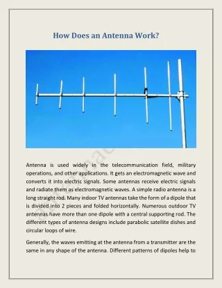
How Does An Antenna Work
Antenna is used widely in the telecommunication field, military operations, and other applications. It gets an electromagnetic wave and converts it into electric signals. Some antennas receive electric signals and radiate them as electromagnetic waves. A simple radio antenna is a long straight rod. Many indoor TV antennas take the form of a dipole that is divided into 2 pieces and folded horizontally. Numerous outdoor TV antennas have more than one dipole with a central supporting rod. The different types of antenna designs include parabolic satellite dishes and circular loops of wire.
7 views • 5 slides

Miniature Pinscher
Explore our adorable Miniature Pinscher puppies available at Westchester Puppies and Kittens. Find your perfect furry companion today and bring home a loyal and playful Miniature Pinscher. https://www.westchesterpuppies.com/miniature-pinscher
10 views • 6 slides

Miniature Substation
Elevate your electrical infrastructure with Tristar Electrical , a leading manufacturer of top-quality miniature substations (mini subs). Our expertise in designing and producing mini subs ensures reliable and efficient power distribution solutions for a range of applications. Whether for industrial complexes, commercial buildings, or residential projects, Tristar's miniature substations are engineered for durability, safety, and optimal performance. Trust Tristar Electrical as your go-to mini sub manufacturer for customized solutions that meet your project's unique requirements.
10 views • 4 slides
Open Access is an initiative that aims to make scientific research freely available to all. To date our community has made over 100 million downloads. It’s based on principles of collaboration, unobstructed discovery, and, most importantly, scientific progression. As PhD students, we found it difficult to access the research we needed, so we decided to create a new Open Access publisher that levels the playing field for scientists across the world. How? By making research easy to access, and puts the academic needs of the researchers before the business interests of publishers.
We are a community of more than 103,000 authors and editors from 3,291 institutions spanning 160 countries, including Nobel Prize winners and some of the world’s most-cited researchers. Publishing on IntechOpen allows authors to earn citations and find new collaborators, meaning more people see your work not only from your own field of study, but from other related fields too.
Brief introduction to this section that descibes Open Access especially from an IntechOpen perspective
Want to get in touch? Contact our London head office or media team here
Our team is growing all the time, so we’re always on the lookout for smart people who want to help us reshape the world of scientific publishing.
Home > Books > Progress in Compact Antennas
Miniature Antenna with Frequency Agility
Submitted: 11 September 2013 Published: 10 September 2014
DOI: 10.5772/58838
Cite this chapter
There are two ways to cite this chapter:
From the Edited Volume
Progress in Compact Antennas
Edited by Laure Huitema
To purchase hard copies of this book, please contact the representative in India: CBS Publishers & Distributors Pvt. Ltd. www.cbspd.com | [email protected]
Chapter metrics overview
3,401 Chapter Downloads
Impact of this chapter
Total Chapter Downloads on intechopen.com
Total Chapter Views on intechopen.com
Author Information
- University of Limoges, Xlim Laboratory, France
T. Monediere
*Address all correspondence to:
1. Introduction
The need of both mobility and communication leads to the integration of antennas in miniature devices so far non-connected (particularly in medical areas). The dedicated volume for the antenna, including its ground plane, has to be kept at its acceptable minimum, involving low bandwidth. Moreover, due to their poor impedance bandwidth, small antennas tend to be very sensitive to the environment. Indeed, they are directly affected by their immediate surroundings, which disturb their working band, their radiation and their performances [ 1 ]. To counter the low bandwidth of the antenna and to adapt it to variable conditions and surroundings, it can integrate active components.
Thus, active components become highly suitable for the development of modern wireless communications. Indeed, they allow the miniaturization, shifting the antenna working frequency to be matched over a wide bandwidth by covering only the user channel and the adaptation of antennas to variable operating conditions and surroundings. It is in this framework that authors will propose in this chapter to detail the integration of active components in antennas to be more compact, smart and integrated.
The first part will address an overview of the most common used techniques for compact antennas to become active. In this goal, active antennas state-of-the-art will be presented:
The first sub-section will present antennas integrating tunable components such as varactor diodes, MicroElectroMechanical systems (MEMS), Positive Intrinsic Negative (PIN) diode and Field Effect Transistor (FET).
The second sub-section will focus on active antennas using tunable materials properties, i.e. ferroelectric materials and liquid crystal.
A second part will show relevant parameters for active antennas studies. It will exhibit both challenges and how to integrate active components in order to maximize the antenna performances and efficiency. This part will be supported by concrete examples. Therefore, depending on their intended applications, readers will be prepared to find the best trade-offs between the agility method, the miniaturization and antenna performances.
The last part will be dedicated to present limitations of actual and most common solutions proposed for active and compact antennas. In this framework, new approaches will be detailed to overcome these physical limitations.

2. Overview of compact active antennas
Very small size antennas are needed for future dense wireless network deployment, for example in WBAN (Wireless Body Area Network) where the size is limited to dimensions much smaller (hearing aid, implants) than wavelength (λ 0 =12.2 cm at 2.45GHz) or for the DVB-H (Digital Video Broadcasting – Handheld) application, where the miniaturization aspect is even more critical because it is a low frequency standard (λ 0 =60 cm at 470 MHz). Therefore, the antenna has to be carefully optimized with trading off fundamental size limitations with its characteristics (especially bandwidth and efficiency). In addition, the environment of miniature antennas will be highly variable resulting in large antenna impedance and propagation channel changes. Several challenges have to be addressed. One of them is the adaptive antenna technology for compensating both low bandwidths and detuning effects.
The most commonly cited performance criterion is the achievable frequency tuning range (TR) defined as:
T R ( % ) = 2 ( f max − f min ) f max + f min .100 where f max and f min are respectively the upper and the lower antenna operating frequency. The frequency tuning can either be continuous or discrete. The continuous frequency tuning is able to continuously cover each channel of a same standard while the discrete frequency tuning can only switch between different standards. This part will present the most common methods to target frequency tunable antennas design.
2.1. Integration of active components
2.1.1. varactor diodes.
For continuous frequency tuning, the integration of varactor diodes within an antenna is the most common approach [ 2 - 5 ]. P. Bhartia et al. were the first to publish antenna integrating varactor diodes [ 6 ]. Indeed, they presented a microstrip patch antenna with varactor diodes at the edges of the structure, as illustrated Figure 1 . Both rectangular and circular tunable patches were studied, results reveal that 22% and 30% of bandwidth can respectively be achieved by varying the DC-bias-voltage between 0V and 30V.

Patch antenna integrating varactor diodes [ 28 ]
Slot antennas are also good candidates for the frequency agility [ 7 - 9 ]. N. Behdad and K. Sarabandi presented in [ 9 ] a dual band reconfigurable slot antenna. The schematic of its proposed dual-band slot antenna is shown in Figure 2 . Matching is performed by choosing appropriately the location of the microstrip feed and the length of the open circuited line.

Dual reconfigurable slot antenna [ 9 ]
Figure 3 shows the simulated and measured dual-band responses of the antenna where by applying the appropriate combination of bias voltages (V 1 and V 2 ) the frequency of the first band is kept fixed and that of the second band is tuned. Similarly, as shown in Figure 3 , it is possible to keep the frequency of the second band stationary and sweep the frequency of the first band.

Measured |S 11 | parameters for different combination of bias voltages [ 9 ]
Another example show a 3D Inverted F Antenna [ 10 ] designed to cover the entire DVB-H band going from 470 MHz to 862 MHz. To be integrated in a mobile handheld device, the antenna allocated volume had to be very compact. A good trade-off between small sizes and the impedance bandwidth was to choose a structure based on the IFA design. Indeed, the radiating monopole of this kind of structure can be folded all around a material to become more compact (see Figure 4 ).

Inverted F Antenna design (a). Antenna top view (b) [ 10 ]
However, the more compact the antenna is, the lowest the bandwidth is becoming. To counter this issue, it has been proved that using a magneto-dielectric material rather than a dielectric one allows enhancing the input impedance bandwidth. Basing on this antenna design, the idea was to integrate a varactor diode to tune the impedance matching all over the DVB-H band (see Figure 5 ).

Design integrating both magneto-dielectric material and a varactor diode [ 10 ]
A prototype of the tunable antenna has been realized ( Figure 6 ) and measured. For the diode polarization, a DC bias Tee is optimized with SMD components and measured on the DVB-H band ( Figure 6 ). After being validated, it is integrated upstream from the antenna structure as shown Figure 6 . In order to improve the quality and the reliability of wireless links, the final mobile device is integrating two antennas (see Figure 6 ) for diversity operations.

DC bias Tee with SMD components and its integration upstream from the antenna (a), integration of two antennas in the tablet dedicated to the DVB-H reception (b) [ 10 ]
Figure 7 presents respectively the variation of the input impedances and |S 11 | parameters of the antenna versus frequency for different values of the varactor diode bias voltages.

Measured input impedances (a) and |S 11 | parameters (b) for several DC bias voltages [ 10 ]
Therefore, the antenna working band is continuously tuned all over the whole DVB-H band. In the worst case, i.e. for a 2V DC bias voltage, the antenna is matched with |S 11 | <-6dB in a bandwidth which is covering more than one channel of the DVB-H band at-6 dB (largely suitable for the DVB-H standard).
2.1.2. Positive Intrinsic Negative (PIN) diodes
PIN diodes are using as switches:
The ON state of the diode can be modelled by a zero resistance, i.e. a continuous metal strip across the slot where the diode is integrated.
The OFF state of the diode can be modelled as an infinite resistance. The radiating length after the diode is not seen from RF point of view. The effective length of the antenna, and hence its operating frequency, is changing compared with the ON state case.
Selected antenna’s types for integrating PIN diodes are often slot antennas or printed antennas (e.g. printed monopole, Inverted F Antenna, …). J-M. Laheurte presented in [ 11 ] a slot antenna including pin diodes for multi-frequency operation within a frequency octave.

Switchable slot antenna including eight pin diodes [ 11 ]
As shown Figure 8 , this antenna integrates eight PIN diodes and according to their ON or OFF states combination, the antenna can operate at different and discrete frequency bands (see Figure 9 ). Instantaneous impedance bandwidths are between 8% and 21% depending on the diodes’ states combination.

Measured |S 11 | parameters for different states of diodes: all diodes OFF (i), diodes 1, 8 ON (ii), diodes 1, 2, 7, 8 ON (iii) and diodes 1, 2, 3, 6, 7, 8 ON (iv) [ 11 ]
Eventually, this antenna presents somewhat large dimensions since its main size is higher than à λ 0 /2 at 2.8 GHz. The literature presents smaller antennas integrating PIN diodes since their main size are lower than à λ 0 /2 at the working frequency [ 12 ].
Peroulis et al. [ 13 ] presented a tunable single-fed S-shaped slot loaded with a series of four PIN diodes. The effective length modification allows this antenna to operate in one of four selectable frequency bands between 530 and 890 MHz.
Before directly studying the tunable slot antenna, both single S-shaped slot antenna and PIN diodes were separately presented and studied. By this way, the issue related to the design of a suitable PIN switch has been grasped before integrate it and show its effects on the antenna performances. Indeed, to implement the electronic reconfigurability, the ideal shunt switches must be replaced by real PIN diodes. Therefore, the RF equivalent circuit of the diode has been studied (see Figure 10 ) for both the ON and OFF states. The reactive components C p and L p are modeling the packaging effect, while the others come from the electric properties of the diode junction in the ON and OFF positions. Then, the switch bias network was presented as an inductor of 470 nH and three 10 pF capacitors ( Figure 10 ).

RF equivalent circuit of the PIN diode (a) and the switch bias network (b) [ 13 ]
Finally, a reconfigurable slot antenna design ( Figure 11 ) is presented in this paper. Four switches are used in order to tune the antenna over a range of 540–950 MHz. The integration of the fours PIN diodes allows choosing the operating frequency of the antenna ( Figure 11 ).

Reconfigurable slot antenna (a) and its measured |S 11 | parameters (b) [ 13 ]
2.1.3. MicroElectroMechanical systems (MEMS)
MEMS components can allow:
Continuous frequency tuning when they are used as a variable capacitance.
Discrete frequency tuning, when they are used as switches.
E. Erdil presents in [ 14 ] a reconfigurable microstrip patch antenna integrating RF MEMS capacitor for continuously tuning the resonant frequency (see Figure 12 ). The reconfigurability of the operating frequency is obtained by loading one of the radiating edges of the microstrip patch antenna with a CPW stub on which RF MEMS bridge type capacitors are periodically placed.

Frequency tunable microstrip patch antenna integrating MEMS capacitors [ 14 ]
When a DC voltage is applied, the height of the MEMS bridges on the stub is varying, and thus the loading capacitance is also changing. Therefore, as showed Figure 13 the matching frequency around 16.05 GHz shifts down to 15.75 GHz as the actuation voltage is increased from 0 to 11.9 V, where the height of the capacitive gap changes from 1.5 μm to 1.4 μm.

|S 11 |parameters for different actuation voltages and simulation results [ 14 ]
Discrete frequency tuning can be illustrated with a reconfigurable annular slot antenna with a monolithic integration of MEMS actuators presented by B.A. Cetiner in [ 15 ]. The architecture and a photograph of the microstrip-fed reconfigurable antenna annular slot are shown in Figure 14 . The antenna has two concentric circular slots. According to MEMS switch S 1 state, they can be individually excited in order to achieve frequency reconfigurability. S 2 and S 3 switches enable the metallic annular ring, which stays between the outer and inner slots, to be shorted to RF ground.

Microstrip feeding line integrating a single-arm MEMS switch (a) and the annular slot integrating two double-arm MEMS actuators [ 15 ]
The measured |S 11 | parameters ( Figure 15 ) show that when MEMS switches are activated (down-state) by applying DC bias voltages, the antenna working band is around 5.2 GHz. Vice-versa, when MEMS switches are in the up-state, the antenna is working at 2.4 GHz.

Measured and simulated |S 11 |parameters for MEMS switches activated (5.2 GHz) and deactivated (2.4 GHz) [ 15 ]
2.1.4. Field Effect Transistor
Continuous frequency tuning can be achieved by using Field Effect Transistor. In [ 16 ], S. Kawasaki presents a slot antenna loaded with two one-port reactive FET. The electrically length of the slot is changing according to the voltage bias applying on the FET. The measured |S 11 | parameters (see Figure 16) show a 10% frequency tuning range for a gate tuning voltage (V gs ) going from 0V to-0.6V while the drain voltage (V ds ) is tuned from 0V to 0.4V.

Measured |S 11 |parameters for both gate and drain tuning voltages [ 16 ]
2.2. Agile antennas using tunable materials
Changing the material characteristics in a part of antenna designs also promise the ability to tune them in frequency. The application of a static electric field can be used to change the relative permittivity of a ferroelectric material or a liquid crystal, respectively a static magnetic field can changed the relative permeability of a ferrite. In case of printed antennas, these changes modify the effective electrical length of antennas, and then resulting in shifts of their operating frequencies.
2.2.1. Ferroelectric materials
Lead-based perovskite ceramics such as PbZr x Ti 1−x O 3 (PZT) have been the leaders, for the past 50 years, on ferroelectric material research [ 17 ] for electronic devices, sensors, actuators, and medical ultrasonic transducers, owing to their good dielectric properties over a wide temperature range. Due to health care and environmental regulations, restriction of hazardous substances as lead has been required [ 18 ]. Since the last 10 years, many efforts have been mainly devoted in the field of microwave applications to Ba x Sr 1-x TiO 3 (BST) material which is one of the most attractive materials [ 19 ] because it presents high dielectric constant, relatively low dielectric loss, interesting tunability and small temperature dependence. In fact, in BST, the Curie temperature (Tc) which defines the ferroelectric/paraelectric transition is tuned by controlling the Ba/Sr ratio. More recently some other ferroelectric ceramics such as the tantalate niobate oxide KTa x Nb 1−x O 3 (KTN) or the sodium bismuth titanate Na 0.5 Bi 0.5 TiO 3 (BNT) and its solid solutions BNT-BT are emerging.
Two different methods exist to polarize a ferroelectric material with a static electric field. A better tunability is obtained when the static electric field is perpendicular to the two electrodes. For antenna application point of view, antenna designs integrating ferroelectric materials have to move toward this kind of polarization in order to have a better reconfigurability. However, many efforts have to be devoted from realization and also simulation point of views. Therefore, compact antenna community exhibits only few papers of this kind of antennas.
V. K. Palukuru et al. [ 20 ] present a tunable antenna using an integrated ferroelectric-thick film made of BST material. The antenna is depicted in Figure 17 . It exhibits a folded slot antenna loading with a BST thin film varactor. In order to tune the dielectric permittivity of the BST film, a DC bias voltage is applied thanks to a bias-T component, which was attached to the Vector Network Analyzer. The BST varactor is placed over the radiating slot: the upper electrode (0.2 mm 0.2 mm) is part of the antenna’s metallization and the lower electrode is the antenna’s ground plane. In order to reduce the capacitance of the varactor, a slight horizontal offset is used between the electrodes. Therefore, the electric field for biasing the material is both in the vertical and the horizontal directions.

Folded slot antenna with the BST varactor (a), side cross-section (b) and top view (c) of the BST varactor [ 20 ]
The |S 11 | parameters ( Figure 18 ) show that a frequency tunability of 3.5% can be obtained with a change of the bias voltage from 0V to 200V.

Measured |S 11 |parameters for different DC-bias voltages [ 20 ]
H. Jiang presents a coplanar waveguide (CPW) square-ring slot antenna as showed Figure 19 [ 21 ]. Nine shunt ferroelectric BST thin film varactors are integrated with the CPW antenna structure achieving both antenna miniaturization and reconfiguration.

Coplanar waveguide square-ring slot antenna integrating BST material [ 21 ]
Figure 20 shows the measured |S 11 |parameter with DC bias voltages from 0 V to 7 V. Therefore the antenna working band is continuously tuned from 5.28 GHz up to 5.77 GHz.

Measured |S 11 |parameters for different DC-bias voltages [ 21 ]
2.2.2. Liquid crystal
Another technological approach for designing an agile antenna is the use of liquid crystal as a tunable dielectric. Indeed, the characterizations of liquid crystals [ 22 - 24 ] have shown that they are promising tunable materials for microwave applications, especially for operating frequencies above 10 GHz. The material features low dielectric loss and continuous tunability with low bias power consumption. The literature show that some microwave applications are using liquid crystals, e.g. for polarization agile antenna [ 25 ], tunable patch antennas [ 26 ], reflectarrays [ 27 - 28 ], filters [ 29 ], resonators [ 30 ] and variable delay lines [ 31 - 33 ].
In this framework, L. Liu presents in [ 34 ] a tunable patch antenna using a liquid crystal. Its operating frequency is around 5 GHz with a tuning range around 4% in measurement. The Figure 21 presents the antenna geometry composed of three layers of Taconic substrate. The liquid crystal is injected in the middle layer just under the microstrip patch and between the ground plane and patch top hat. A DC bias voltage was applied between the patch and ground across the liquid crystal using a bias tee at the feed input.

Tunable patch antenna using a liquid crystal [ 34 ]
The Figure 22 shows the measured return losses for the patch antenna for three states of liquid crystal bias: 0V, 5V and 10V. The 0V state reveals that the used liquid crystal without DC bias presents somewhat high losses around 0.12 for the loss tangent. Thus a 4% frequency tuning can be achieved with relatively poor radiation efficiencies, i.e. 14% at least (at 0V) to 40% (at 10V).

Measured |S 11 |parameters for different DC-bias voltages [ 34 ]
2.2.3. Ferrite materials
Frequency-tuned ferrite-based antennas are rarely presented in the literature. In [ 35 ] and [ 36 ], authors study patch antennas on ferrite substrates ( Figure 23 ) whereas A. Petosa presents in [ 37 ] a ferrite resonator antenna. In this latter, biasing of the ferrite with a static magnetic field is achieved using a permanent magnet. The magnet was located under the ferrite antenna beneath the ground plane. For a parallel magnetic-bias orientation, the resonance frequency can be tuned on 8% of bandwidth. That scales to 9% for a perpendicular magnetic-bias orientation.

Patch antenna on a ferrite substrate [ 37 ]
All results presented in the literature and investigated the properties of ferrite-based microstrip antennas indicate that factors including non-uniform bias fields and the multiple modal field distributions excited in a bulk ferrite substrate may preclude their use in practical applications.
Now that an overview of the most common used techniques for compact antennas to become active has been presented, the next part will address both challenges and how to integrate active components in order to maximize the antenna performances and efficiency.
3. Relevant parameter for frequency agile antenna studies – New approach for wireless applications.
3.1. how to integrate an active component – challenges.
To implement the reconfigurability in an antenna, the knowledge of the active component or the tunable material is essential. Even in case of commercial components, as varactor or PIN diodes, users and particularly the microwave community do not have enough parameters and information at RF frequencies. Some papers detail the integration of the RF equivalent circuit of the used component [ 10 ],[ 13 ].
The varactor diodes integrated in an antenna for frequency reconfigurability is the most popular way. Thus, this section will focus on varactor diodes issues. However, arguments can be extended to other frequency tuning methods.
In [ 10 ], the paper completes the lack of information related to most of varactor diode datasheets. Indeed, constructor only provide characteristics at low frequencies and do not give enough parameters for antenna application point of view, such as capacitance values, serial resistance and accepted power at RF frequencies. The chosen varactor in this paper has been characterized according to antenna designer criteria and its electromagnetic model has been deduced. This example is chosen in the framework of this chapter.
To correctly explain this example, the next subsection will investigate the place where the varactor can be integrated. Following the presentation of the varactor diode manufacturer’s datasheet, a complete characterization meeting antenna designer’s criteria will be explained. That will lead to the determination of the varactor diode S parameters. With the knowledge of the latter, two methods will be explained and described to reach an accurate antenna simulation and realization:
The electromagnetic equivalent circuit of the varactor diode can be deduced from the S parameters thanks to Agilent ADS.
The S parameters of the varactor diode can be directly injected in the electromagnetic simulator CST Microwave Studio ® and the antenna performances deduced thanks to a co-simulation.
3.1.1. Varactor diode area in an antenna
The varactor diode is a tunable capacitor which loads the antenna in order to artificially increase its electrical length. To be the most efficient, it must be placed where the electrical field is maximum. Take a folded Inverted F Antenna for example presented Figure 24 . The maximum of the electrical field is at the end of the radiating element (see Figure 24 ). To be integrated at this place and joined the ground plane at the same time, the varactor diode can be soldered between the ribbon and the ground. In most cases, DC-block capacitors have to be added for the varactor’s DC-bias not to be shunt.

Inverted F Antenna Measured (a) and the total electric field on the radiating element (b)
3.1.2. Varactor diode datasheet
In [ 10 ], the chosen GaAs hyperabrupt varactor diode MGV125-22 (Aeroflex Metelics) [ 38 ] has a capacity range between 0.2 pF and 2 pF for 0 to 22 Volts tuning voltage as shown Figure 25 . However, these values are given as a rough line and the datasheet does not give enough parameters for high frequencies antenna application’s point of view. Indeed, the values for junction capacitance C j ( Figure 25 ) and the quality factor Q are supplied by the manufacturer and are almost always specified at a low frequency. The Figure 25 shows the widely used varactor diode model with L p and C p the values of the package inductance and capacitance.

Manufacturer’s capacitance value (extracted at 1MHz) versus the DC bias voltage (a) and the Varactor diode model (b)
In the MGV125-22 case, junction capacitance values are specified at 1 MHz and the Q factor equals 3000 at 50 MHz for a DC bias voltage of –4 Volts. Q is defined by Q=1/(ωC j R s ). This formula can be used to calculate the series resistance R s of the varactor model at the measured frequency, its value is assumed to be constant with reverse voltage. Thus, at 50 MHz R s =1.06Ω. It is important to note that R s impacts directly the antenna total efficiency. A too high value (from 3Ω) is basically penalizing for antenna performances. This enhances the need to assess its value at microwave frequencies. For this purpose, the hyperabrupt varactor diode has to be characterized close to operating conditions (here between 470 MHz and 862 MHz).
3.1.3. Varactor diode characterization
First method: Electromagnetic model
The varactor diode is soldered on a 50 Ω impedance microstrip line as shown Figure 26 . A dedicated TRL (Through-Reflect-Line) calibration kit is manufactured ( Figure 26 ) in order to de-embed both connectors and lines. Thus S parameters of the single varactor diode can be deduced. Considering the varactor diode model previously presented in Figure 26 , C j , L p , C p and R s values can be deduced for each voltage and for a constant injected power of-10 dBm. Therefore, model component values are adjusted (see Figure 26 ) in order their S parameters to correspond with the measured ones. The Figure 26 shows the comparison between S parameters of the determined electromagnetic model (Agilent ADS) and the measured ones for 2 Volts and 10 Volts DC bias voltages.

Characterization of the varactor diode (a) and the Comparison between the electromagnetic model and the measurement on S 11 parameter on the [400 MHz – 1 GHz] frequency band (b)
These results are given as an example and the same work has been done for varactor reverse bias voltages varying from 2V to 22V with a 2V step. As expected, the corresponding electromagnetic model presents constant values according to the DC bias voltage ( Figure 27 ): L p =3.821nH, C p =0.08pF and R s =1.8Ω. The C j value presented in Figure 27 decreases as a function of DC bias voltage value.

Electromagnetic model with the capacitance values C j versus the DC bias voltage (b)
Second method: Co-simulation
Another way is to directly insert the S parameters touchstone file of the varactor diode in the antenna electromagnetic simulation as illustrated in Figure 28 .

Co-simulation of the antenna including measured S parameters of the diode
Thanks to the previous TRL calibration, only the varactor diode S parameters are inserted in the simulator. By this way, both antenna and varactor diode are combined and the S parameters of the global device can be directly simulated. An example (presented paragraph 3.3) will confirm that the two previous methods exhibit similar antenna performances.
3.2. Limitations of currently varactor diode method – Power characterization
Figure 29 provides some information regarding the accepted power by the varactor diode: high injected power involves some varactor diode distortions.

Measured S parameters according to the injected power
This figure presents S parameters of the diode for only three values of injected power:-10 dBm, 0 dBm and 10 dBm. The non-linear distortion of the diode has been studied. It reveals that the varactor diode model well fits measurements for an injected RF power lower than-5 dBm. Beyond this injected power (see for 0 dBm), no varactor model can fit the measurement. Regarding antenna’s parameters, the following example will show that a large RF power (upper than-5 dBm) involves a mismatched antenna. As far as the DVB-H application, the system is only working in receiving mode, the diode distortion will never appear and the linear electromagnetic model can be used and integrated in the electromagnetic simulator. Indeed, for receiver devices, the antenna accepted power is far lower than – 5 dBm.
3.3. Example of a basic tunable DVB-H antenna
This subsection investigates an example to show the interest of the previous varactor diode characterization. This was briefly presented in [ 4 ], it is completed here by adding the first method (electromagnetic model) and the power characterization. A basic IFA prototype loaded by the same varactor diode (see Figure 30 ) has been manufactured.

Basic IFA prototype
It has been measured for a-10 dBm RF power and its performances compared with three simulations: with both presented methods and with the varactor diode’s datasheet ( Figure 31 ). |S 11 | parameters show that both investigated methods and measurement present a good agreement. Moreover, they are different from |S 11 | parameters determined with the varactor diode datasheet. That underlines the relevance of the varactor diode characterization. Regarding the antenna total efficiency, it equals 50 % in the real case whereas it reaches 60% when the varactor datasheet is used in electromagnetic simulations.
Power characterization is illustrated on Figure 31 . This figure reminds the measured |S 11 | parameter for a power of-10 dBm. For a 10 dBm injected power, the measured |S 11 | parameter is compared with the simulated one with the second method.

|S 11 | parameters for the different methods (a) and according to the injected power (b)
There is a good agreement between the measurement and the simulation. This figure shows that the non-linearity of the varactor diode disturbs the |S 11 | parameter of the antenna. Thus, this kind of varactor diode has to be used only for reception devices.
Therefore, this section has presented how to integrate and characterize a varactor diode. It reveals the importance of the diode characterization in a design flow dedicated to antenna structure.
3.4. Discussion and trade-offs between agility techniques and physical limitations
According to the aimed application, trade-offs are necessary to design a frequency tunable antenna.
For discrete frequency tuning, PIN diodes or MEMS switches can be planed.
For continuous frequency tuning, which is often aiming for compact antennas, varactor diodes, MEMS variable capacitor and tunable materials can be used.
However, previous paragraphs have revealed that varactor diodes are not usable for transmitter devices because of their non-linearity for considering power levels.
The RF characterization of ferroelectric films shows high power handling capability [ 39 ]. Good permittivity tunability may be obtained if both materials properties and variable capacitor sizes have been properly dimensioned. The conclusion is the same for MEMS variable capacitor.
Studies on both ferroelectric material and MEMS capacitor merit extended investigations because these solutions seem to be the best and most promising alternatives faced with varactor diodes.
Performing rigorous full-wave analysis of these new components is the new challenge to extract their accurate electromagnetic models. Antennas would be optimized by considering the real response of these components. These investigations would enable the co-development of antennas integrating components’ electromagnetic models.
4. Conclusion
To conclude, an overview of compact and frequency agile antenna has been presented and detailed in this chapter while mentioning a lot of literature references. A special part has been dedicated to the presentation of the most common method to achieve a frequency tuning: the use of varactor diodes. Their integration within an antenna to be the most efficient has been shown. The study exhibits varactor diodes characterization and also reveals their limitation. A summary of the presented methods according to the intended application has been presented. Eventually, some ideas on varator diodes alternatives have been proposed in order to make antenna tunability viable for transmitter devices.
- 1. Huitema, L.; Sufyar, S.; Delaveaud, C.; D'Errico, R., "Miniature antenna effect on the ear-to-ear radio channel characteristics," Antennas and Propagation (EUCAP), 2012 6th European Conference on , vol., no., pp.3402,3406, 26-30 March 2012
- 2. Libo Huang; et al., "Electrically Tunable Antenna Design Procedure for Mobile Applications," Microwave Theory and Techniques, IEEE Transactions on , vol.56, pp.2789-2797, Dec. 2008
- 3. Li, Y., Zhang, Z., Chen, W., Feng, Z. and Iskander, M. F. (2010), A compact DVB-H antenna with varactor-tuned matching circuit. Microw. Opt. Technol. Lett., 52: 1786–1789
- 4. Huitema, L.; Reveyrand, T. et al., "A compact and reconfigurable DVB-H antenna for mobile handheld devices," Antennas and Propagation (EUCAP), Proceedings of the 5th European Conference on , vol., no., pp.1314-1317, 11-15 April 2011
- 5. Canneva, F.; Ribero, J.; Staraj, R., "Tunable antenna for DVB-H band," Antennas and Propagation (EuCAP), 2010 Proceedings of the Fourth European Conference on , vol., no., pp.1,3, 12-16 April 2010
- 6. Bhartia, P.; Bahl, I.J., "A frequency agile microstrip antenna," Antennas and Propagation Society International Symposium, 1982 , vol.20, no., pp.304,307, May 1982
- 7. Erfani, E.; Nourinia, J.; Ghobadi, C.; Niroo-Jazi, M.; Denidni, T.A., "Design and Implementation of an Integrated UWB/Reconfigurable-Slot Antenna for Cognitive Radio Applications," Antennas and Wireless Propagation Letters, IEEE , vol.11, no., pp.77,80, 2012
- 8. Behdad, N.; Sarabandi, K., "A varactor-tuned dual-band slot antenna," Antennas and Propagation, IEEE Transactions on , vol.54, no.2, pp.401,408, Feb. 2006
- 9. Behdad, N.; Sarabandi, K., "Dual-band reconfigurable antenna with a very wide tunability range," Antennas and Propagation, IEEE Transactions on , vol.54, no.2, pp.409,416, Feb. 2006
- 10. Huitema, L.; Reveyrand, T.; Mattei, J.-L.; Arnaud, E.; Decroze, C.; Monediere, T., "Frequency Tunable Antenna Using a Magneto-Dielectric Material for DVB-H Application," Antennas and Propagation, IEEE Transactions on , vol.61, no.9, pp.4456,4466, Sept. 2013
- 11. Laheurte, J.-M., "Switchable CPW-fed slot antenna for multifrequency operation," Electronics Letters , vol.37, no.25, pp.1498,1500, 6 Dec 2001
- 12. Outi Kivekäs, Jani Ollikainen, and Pertti Vainikainen, “Frequency-tunable internal antenna for mobile phones”, 12th International Symposium on Antennas (JINA 2002). Nice, France, 12-14 November 2002, volume 2, pages 53-56
- 13. Peroulis, D.; Sarabandi, K.; Katehi, L. P B, "Design of reconfigurable slot antennas," Antennas and Propagation, IEEE Transactions on , vol.53, no.2, pp.645,654, Feb. 2005
- 14. Erdil, Emre; Topalli, K.; Unlu, M.; Civi, O.A.; Akin, T., "Frequency Tunable Microstrip Patch Antenna Using RF MEMS Technology," Antennas and Propagation, IEEE Transactions on , vol.55, no.4, pp.1193,1196, April 2007
- 15. Cetiner, B.A.; Crusats, G.R.; Jofre, L.; Biyikli, Necmi, "RF MEMS Integrated Frequency Reconfigurable Annular Slot Antenna," Antennas and Propagation, IEEE Transactions on , vol.58, no.3, pp.626,632, March 2010
- 16. Kawasaki, S.; Itoh, T., "A slot antenna with electronically tunable length," Antennas and Propagation Society International Symposium, 1991. AP-S. Digest , vol., no., pp.130,133 vol.1, 24-28 June 1991
- 17. N. Setter, D. Damjanovic, et al., Ferroelectric thin films: Review of materials, properties, and applications, J. Appl. Phys. 100, (2006)
- 18. P. K. Panda, Review: environmental friendly lead-free piezoelectric materials, J. Mater. Sci. 44, 5049–5062, (2009)
- 19. A. K.Tagantsev, V. O. Sherman, K. F. Afanasiev, J. Venkatesh and N. Setter, Ferroelectric Materials for Microwave Tunable Applications, J. Electroceram., 11, 5-66, 2003
- 20. Palukuru, V.K.; Komulainen, M.; Tick, T.; Perantie, J.; Jantunen, Heli, "Low-Sintering-Temperature Ferroelectric-Thick Films: RF Properties and an Application in a Frequency-Tunable Folded Slot Antenna," Antennas and Wireless Propagation Letters, IEEE , vol.7, no., pp.461,464, 2008
- 21. Hai Jiang; Patterson, M.; Brown, D.; Chenhao Zhang; KuanChang Pan; Subramanyam, G.; Kuhl, D.; Leedy, K.; Cerny, C., "Miniaturized and Reconfigurable CPW Square-Ring Slot Antenna Loaded With Ferroelectric BST Thin Film Varactors," Antennas and Propagation, IEEE Transactions on , vol.60, no.7, pp.3111,3119, July 2012
- 22. Schaub, D.E.; Oliver, D.R., "A Circular Patch Resonator for the Measurement of Microwave Permittivity of Nematic Liquid Crystal," Microwave Theory and Techniques, IEEE Transactions on , vol.59, no.7, pp.1855,1862, July 2011
- 23. Mueller, S.; Penirschke, A.; Damm, C.; Scheele, P.; Wittek, M.; Weil, Carsten; Jakoby, R., "Broad-band microwave characterization of liquid crystals using a temperature-controlled coaxial transmission line," Microwave Theory and Techniques, IEEE Transactions on , vol.53, no.6, pp.1937,1945, June 2005
- 24. Bulja, S.; Mirshekar-Syahkal, D.; James, R.; Day, S.E.; Fernandez, F.A., "Measurement of Dielectric Properties of Nematic Liquid Crystals at Millimeter Wavelength," Microwave Theory and Techniques, IEEE Transactions on , vol.58, no.12, pp.3493,3501, Dec. 2010
- 25. Karabey, O.H.; Bildik, S.; Bausch, S.; Strunck, S.; Gaebler, A.; Jakoby, R., "Continuously Polarization Agile Antenna by Using Liquid Crystal-Based Tunable Variable Delay Lines," Antennas and Propagation, IEEE Transactions on , vol.61, no.1, pp.70,76, Jan. 2013
- 26. Luyi Liu; Langley, R., "Electrically small antenna tuning techniques," Antennas & Propagation Conference, 2009. LAPC 2009. Loughborough , vol., no., pp.313,316, 16-17 Nov. 2009
- 27. Wenfei Hu; Arrebola, M.; Cahill, R.; Encinar, J.A.; Fusco, V.; Gamble, H.S.; Alvarez, Y.; Las-Heras, F., "94 GHz Dual-Reflector Antenna With Reflectarray Subreflector," Antennas and Propagation, IEEE Transactions on , vol.57, no.10, pp.3043,3050, Oct. 2009
- 28. Yazdanpanahi, M.; Bulja, S.; Mirshekar-Syahkal, D.; James, R.; Day, S.E.; Fernandez, F.A., "Liquid-crystal-based mm-wave tunable resonator," Microwave Conference (EuMC), 2010 European , vol., no., pp.1233,1236, 28-30 Sept. 2010S.P.; Grant, N., "Phase agile reflectarray cells based on liquid crystals," Microwaves, Antennas & Propagation, IET , vol.1, no.4, pp.809,814, Aug. 2007
- 29. Goelden, F.; Gaebler, A.; Karabey, O.; Goebel, M.; Manabe, A.; Jakoby, R., "Tunable band-pass filter based on Liquid Crystal," German Microwave Conference, 2010 , vol., no., pp.98,101, 15-17 March 2010
- 30. Yazdanpanahi, M.; Bulja, S.; Mirshekar-Syahkal, D.; James, R.; Day, S.E.; Fernandez, F.A., "Liquid-crystal-based mm-wave tunable resonator," Microwave Conference (EuMC), 2010 European , vol., no., pp.1233,1236, 28-30 Sept. 2010
- 31. Kuki, T.; Fujikake, H.; Nomoto, T., "Microwave variable delay line using dual-frequency switching-mode liquid crystal," Microwave Theory and Techniques, IEEE Transactions on , vol.50, no.11, pp.2604,2609, Nov 2002
- 32. Goelden, F.; Gaebler, A.; Goebel, M.; Manabe, A.; Mueller, S.; Jakoby, R., "Tunable liquid crystal phase shifter for microwave frequencies," Electronics Letters , vol.45, no.13, pp.686,687, June 18 2009
- 33. Karabey, O.H.; Goelden, F.; Gaebler, A.; Strunck, S.; Jakoby, R., "Tunable loaded line phase shifters for microwave applications," Microwave Symposium Digest (MTT), 2011 IEEE MTT-S International , vol., no., pp.1,1, 5-10 June 2011
- 34. Liu, L.; Langley, R.J., "Liquid crystal tunable microstrip patch antenna," Electronics Letters , vol.44, no.20, pp.1179,1180, September 25 2008
- 35. Brown, A.D.; Volakis, J.L.; Kempel, Leo C.; Botros, Y.Y., "Patch antennas on ferromagnetic substrates," Antennas and Propagation, IEEE Transactions on , vol.47, no.1, pp.26,32, Jan 1999
- 36. Mishra, R.K.; Pattnaik, S.S.; Das, N., "Tuning of microstrip antenna on ferrite substrate," Antennas and Propagation, IEEE Transactions on , vol.41, no.2, pp.230,233, Feb 1993
- 37. Petosa, A.; Mongia, R.K.; Cuhaci, M.; Wight, J.S., "Magnetically tunable ferrite resonator antenna," Electronics Letters , vol.30, no.13, pp.1021,1022, 23 Jun 1994
- 38. Aeroflex Metelics datasheet , Available: http://www.aeroflex.com/AMS/Metelics/pdfiles/MGV_Series_Hyperabrupt_A17041.pdf
- 39. Laur, V.; Costes, R.; Houndonougbo, F.; et al., "Microwave study of tunable planar capacitors using mn-doped ba 0.6 sr 0.4 tio 3 ceramics," Ultrasonics, Ferroelectrics and Frequency Control, IEEE Transactions on , vol.56, no.11, pp.2363-2369, November 2009
© 2014 The Author(s). Licensee IntechOpen. This chapter is distributed under the terms of the Creative Commons Attribution 3.0 License , which permits unrestricted use, distribution, and reproduction in any medium, provided the original work is properly cited.
Continue reading from the same book
Published: 10 September 2014
By Y. Taachouche, M. Abdallah, F. Colombel, G. Le Ray...
2985 downloads
By Alexandr E. Krasnok, Pavel A. Belov, Andrey E. Mir...
3192 downloads
By Fabio Viola and Pietro Romano
3042 downloads

- My presentations
Auth with social network:
Download presentation
We think you have liked this presentation. If you wish to download it, please recommend it to your friends in any social system. Share buttons are a little bit lower. Thank you!
Presentation is loading. Please wait.
Miniature Antenna: Results and Proposed Work March 2008.
Published by Bruce Cox Modified over 9 years ago
Similar presentations
Presentation on theme: "Miniature Antenna: Results and Proposed Work March 2008."— Presentation transcript:

Practical Radio design

GTEM CABLE EMISSION STUDIES MEASUREMENT TECHNOLOGY LIMITED JUNE 29 TH 2010 Dr. Zaid Muhi-Eldeen Al-Daher Dr. Angela Nothofer Prof. Christos Christopoulos.

EMLAB 1 4. Linear wire antenna. EMLAB 2 Simulation of dipole antennas.

Introduction to Antennas Dipoles Verticals Large Loops Yagi-Uda Arrays

Different Types of Antennas

Outline We will see main families of antenna used to create a radiated radio wave: wire antennas (dipole, monopole Yagi) slot antennas (half or quarter.

Foundation Licence Feeders and Antennas. What they do Feeder: transfers RF current between a transceiver and antenna without radiating radio waves. (Hope.

Nasimuddin1 and Karu Esselle2

A Conformal CPW Folded Slot Antenna Array Printed on a Kapton Substrate Masud A. Aziz Sayan Roy* Layne A. Berge Irfanullah Sanjay Nariyal Benjamin D. Braaten.

A NEW PRINTED QUASI-LANDSTORFER ANTENNA

Chapter 6 Antennas Antenna Basics

Antennas Lecture 9.

Faisal Abedin Advisor: Dr. Mohammod Ali

Antenna Primer Wang Ng. References Balanis; Antenna Theory Collin; Antennas and Radiowave Propagation.

A COMPACT FOAM-BASED UHF PIFA Shashank Kulkarni and Sergey Makarov ECE Dept, WPI, 100 Institute Rd., Worcester, MA Introduction Modeling work is.

A Multilayered Broadband Reflect-Array Manuel Romero.

Antennas and Radiation

Joe Horanzy AA3JH April 4th, 2013 K3DN Presentation

Training materials for wireless trainers Antennas and Transmission Lines.
About project
© 2024 SlidePlayer.com Inc. All rights reserved.
IEEE Account
- Change Username/Password
- Update Address
Purchase Details
- Payment Options
- Order History
- View Purchased Documents
Profile Information
- Communications Preferences
- Profession and Education
- Technical Interests
- US & Canada: +1 800 678 4333
- Worldwide: +1 732 981 0060
- Contact & Support
- About IEEE Xplore
- Accessibility
- Terms of Use
- Nondiscrimination Policy
- Privacy & Opting Out of Cookies
A not-for-profit organization, IEEE is the world's largest technical professional organization dedicated to advancing technology for the benefit of humanity. © Copyright 2024 IEEE - All rights reserved. Use of this web site signifies your agreement to the terms and conditions.
Compact Antennas for Wireless Communications and Terminals: Theory and Design by Jean-Marc Laheurte
Get full access to Compact Antennas for Wireless Communications and Terminals: Theory and Design and 60K+ other titles, with a free 10-day trial of O'Reilly.
There are also live events, courses curated by job role, and more.
Chapter 9Miniature Antennas 1
9.1. introduction.
The surge in new technologies is enabling more and more features for compact mobile terminals to be presented. Numerous wireless communication standards are being developed, some concurrent, some complementary. For example, it is well known that standards in mobile telephony present a wide coverage and allow a high mobility, while standards in wireless local area networks, such as the IEEE 802.11 standards, enable much higher throughputs, but with poorer coverage and more reduced mobility. A terminal claiming to offer a large range of services with variable throughputs and dynamics should therefore integrate send/receive modules working with several intrinsically different characteristic standards. A common characteristic will, in the case of mobile terminals, always be bulk: with user acceptance assuming a practical and aesthetically pleasing object, then, this being the case, antennas must be as discreet as possible.
Furthermore, each communication standard has been allocated a band of defined working frequencies by the regulatory authorities. As we will see later, the width of the allocated spectrum will directly influence the bandwidth of the antenna and therefore its size. The standards also induce particular characteristics in the performance of the antenna, such as its matching level, the form of radiation created, field polarization, or even a multiplication of the number of antennas for the same standard, as is the ...
Get Compact Antennas for Wireless Communications and Terminals: Theory and Design now with the O’Reilly learning platform.
O’Reilly members experience books, live events, courses curated by job role, and more from O’Reilly and nearly 200 top publishers.
Don’t leave empty-handed
Get Mark Richards’s Software Architecture Patterns ebook to better understand how to design components—and how they should interact.
It’s yours, free.

Check it out now on O’Reilly
Dive in for free with a 10-day trial of the O’Reilly learning platform—then explore all the other resources our members count on to build skills and solve problems every day.


IMAGES
VIDEO
COMMENTS
A miniature antenna is mostly a resonant structure that acts as a transformer, and that translates circuit voltages and currents into a radiated field, or the reverse. Antennas are passive components, reciprocal, and a bit cryptic for most people.
The article presents a miniature antenna with a simple geometry and a simple approach for reconfiguration. In order to make the T-shaped antenna frequency reconfigurable, we integrated Switches in specific positions.
This document summarizes research on different techniques for miniaturizing antennas for wireless applications. It discusses using slots in microstrip patch antennas, high permittivity dielectric substrates, and magneto-dielectric substrates.
Antenna is used widely in the telecommunication field, military operations, and other applications. It gets an electromagnetic wave and converts it into electric signals. Some antennas receive electric signals and radiate them as electromagnetic waves. A simple radio antenna is a long straight rod.
The need of both mobility and communication leads to the integration of antennas in miniature devices so far non-connected (particularly in medical areas). The dedicated volume for the antenna, including its ground plane, has to be kept at its acceptable minimum, involving low bandwidth.
13 Proposed Research for Ultra-Small Antennas Testing plan: –Will have access to a world class anechoic camber at the FDA White Oaks Facility –Antenna measurements at the FDA will be very accurate and help evaluate with precision the gain performance of the various designs. –We will regularly compare our antenna prototypes with ...
Abstract: This paper presents a miniature antenna design for practical applications in wireless low-power low-VHF communications. The proposed antenna is designed to achieve a high gain for a given size (41 cm × 30 cm × 20 cm including a ground plane).
9.1. Introduction. The surge in new technologies is enabling more and more features for compact mobile terminals to be presented. Numerous wireless communication standards are being developed, some concurrent, some complementary.
Generic miniaturization techniques are presented for narrowband, multiband, and wideband antennas. Two chapters devoted to metamaterials antennas and methods to achieve optimal small antennas, as well as a chapter on RFID technologies and related antennas, are included in this comprehensive volume. Coverage includes:
Gale Academic OneFile includes Introduction to miniature antenna and diversity combining techniques by Bar-Giora Goldberg. Click to explore. Use this link to get back to this page.