- Network Sites:
Changing the World One Wireless RF Chip at a Time
- iHeartRadio
- 3D Printing
- Amateur Radio
- Augmented Reality
- Cloud Computing
- Computers & Peripherals
- Consumer Electronics
- Cyber Security
- .NET Gadgeteer
- Adafruit Playground
- AllThingsTalk
- Amazon Alexa
- Amazon Web Services
- Android SmartThings
- Microcontrollers
- Power Electronics
- RF & Wireless
- Sensors & Actuators
- + Start Project
- + Import Project
- Health & Fitness
- Home Automation
- Industrial IoT
- Machine Learning
- Motor Control
- Security / Identification
- AT&T IoT Platform
- BeagleBoard
- Bosch IoT Suite
- ControlEverything.com

Connect With Us
Make diy homework writing machine at home.
Drawing Robot/Pen Plotter/Drawing Machine is an Open Hardware version of the famous machine AxiDraw which it is a pen pl
| 1 | |||
Introduction: Make DIY Homework Writing Machine at Home
Drawing Robot/Pen Plotter/Drawing Machine is an Open Hardware version of the famous machine AxiDraw which it is a pen plotter, capable of writing or drawing on almost any flat surface. It can write with pens, permanent markers, pencils, and other writing implements to handle an endless variety of applications.
Its unique design features a writing head that extends beyond the machine, making it possible to draw on objects bigger than the machine itself. The biggest advantage of the machine is that it can be placed over the book because of the core XY extending design of the machine.
This Drawing Robot/Pen Plotter/Drawing Machine is similar to the commercially available AxiDraw. It is powered by an Arduino Uno controller, uses a CNC Shield, and GRBL firmware
The cost to build the Drawing Robot is between $75 depending on where you buy your parts and whether you already own some of the parts such as the Arduino.
You can find all of my projects on https://www.diyprojectslab.com/
Maximum drawing area 24 * 30 CM.
Thank You NextPCB
This project is successfully completed because of the help and support from NextPCB. Guys if you have a PCB project, please visit their website and get exciting discounts and coupons.
Free shipping 0$ PCB Prototype: https://www.nextpcb.com/pcb-quote?
Thanksgiving Christmas lucky draw 100% win: https://www.nextpcb.com/christmas-lucky-draw
Step 1: Parts and Materials Required
4 x 5/16in washer 4 x M3 washers
2 x Nema 17 Stepper Motors Amazon.com
2 x Linear Rod M8 x 450mm for X Axis Amazon.com
2 x Linear Rod M8 x 350mm for Y Axis Amazon.com
2 x Linear Rod 3mm for Z Axis (you can get it from old CDROM)
1 x Threaded Rod M8 x 480mm8 x LM8UU Bearings Amazon.com
1 x Servo Sg901 x Spring 5m (from ball point pen) Amazon.com
2 x GT2 Pulley, 16 teeth Amazon.com
5 x Bearing 624zz Amazon.com
1 x 2000mm GT2 belt Amazon.com
1 x Arduino Uno Amazon.com
1 x CNC Shield Amazon.com
2 x A4988 Stepper driver with heatsink Amazon.com
6 x Jumpers Amazon.com
1 x 12V 2A Power Supply Amazon.com
- 4 x 5/16in-18
- 13 x Phillips M3-0.5 x 16mm
- 4 x Phillips M3-0.5 x 6mm
- 5 x Phillips M4-0.7x 35mm
- 1 x Hex M3-0.5 x 20mm
- 4 x 5/16in washer
- 4 x M3 washers
Step 2: 3D Printing
PLA is fine for this design. I print at 200C on BuildTak. None of the parts require rafts or brims. I suggest supports only for the pen holder and the Z axis end plate which is standing up.
Download the files from Thingiverse
Open the 3D models in Cura or any other slicer.
Use 75% infill on all the parts (An infill of 70 – 100% will work as well)
Printed all the parts with 0.10 – 0.20 mm layer height
Printed with PLA
Use supports on the Penholder, Slider, X_Support_L and the X_Support_R
Note: The longest part took around 10hrs and the shortest took 30 minutes to print
Step 3: Assemble the X-Axis
Now take the threaded rod and insert it in the hole below. Feed a 5/16in washer and 5/16in nut on both sides of the x-support part
Remember that you need (2) 350mm and (2) 450mm long linear rods
Take the (2) 450mm linear rods and insert them into either x-support part
- Use may need to use a round file to smooth out the holes that you insert them in
- Also, you can use a rubber mallet to help insert the rods
Step 4: Assemble the X-Axis Bearing
Slide the clamshell through the 450mm (X-axis) linear rods Use a rubber mallet again to attach the last X-support on the linear rods Make sure that the rods stick out equally on both sides Slide the other end of the threaded rod through the hole on the X-support Put on the last set of nuts and washers to hold the X-support in place Now that the X-axis is complete, you can use (2) Phillips M3-0.5 x 16mm screws per X-support to help keep the linear rods from sliding
Now you want to push the LM8UU bearings into their place on the top and bottom clamshell (The top and bottom clamshell take (4) bearings each)
Take (4) 624zz bearings and push them through the 3D-printed idler pulleys. Leave the 5th bearing for later when you assemble the Y-axis
Assemble the X-Axis (Carriage)
- Get (4) M3-0.5 x 20mm screws, (4) M3 nuts, (4) M3 washers and (4) 624zz bearings with the idler pulleys installed
- Take one screw and feed a washer through it, the washer will rest on the bearing. The nut will be at the bottom of the carriage, which will secure the bearing in place
Assemble the X-Axis (X-Support)
- Slide the clamshell through the 450mm (X-axis) linear rods
- Use a rubber mallet again to attach the last X-support on the linear rods
- Make sure that the rods stick out equally on both sides
- Slide the other end of the threaded rod through the hole on the X-support
- Put on the last set of nuts and washers to hold the X-support in place
- Now that the X-axis is complete, you can use (2) Phillips M3-0.5 x 16mm screws per X-support to help keep the linear rods from sliding
Step 5: Assemble the Y-Axis
- Slide the the linear rods/Y-back piece through the LM8UU bearings and attach the Y-front piece using a rubber mallet
- Take the (2) 350mm linear rods and insert them the Y-back piece by using a rubber mallet
- Get (1) M4-0.5 x 35 screw, (1) M4 nut and the 5th 624zz bearing
- Get (2) M3-0.5 x 16 screws to secure the linear rods
- Slide in the bearing when inserting the screw through the Y-back piece
Step 6: Assemble the X-Y Axis (Belt)
Use a pair of needle nose pliers to help guide the GT2 belt more easily through the clamshell Take the two ends of the belt and slide them through the “teeth” on the Base Slider The belt should be tight and not loose Note that once the GT2 belt is on, it is normal for the clamshell not to move easily
- Use a pair of needle nose pliers to help guide the GT2 belt more easily through the clamshell
- Take the two ends of the belt and slide them through the “teeth” on the Base Slider
- The belt should be tight and not loose
- Note that once the GT2 belt is on, it is normal for the clamshell not to move easily
Step 7: Assemble the Z-Axis
Get (2) 3mm linear rods and the following 3D printed parts (Slider, Pen Holder, Base Slide, 3MM Metric Thumb Screw) Get (1) Hex M3-0.5 x 20mm screw and the Metric Thumb Screw and push them together. Use superglue to keep it together. Get (3) M3-0.5 x 16mm screws which you will use the secure the Base Slide to the Y-Front part. You may need to use (3) M3-0.5 nuts in order to hold it in place Push the Slider and Pen Holder together to make one piece Now take that new part and the (2) 3mm linear rods and slide the rods through the holes. Place a small spring in between the two parts so there is a little bit of pressure to lift the Slider. You may need to cut the spring a bit until there is an adequate amount of pressure on the slider.
- Get (2) 3mm linear rods and the following 3D printed parts (Slider, Pen Holder, Base Slide, 3MM Metric Thumb Screw)
- Get (1) Hex M3-0.5 x 20mm screw and the Metric Thumb Screw and push them together. Use superglue to keep it together.
- Get (3) M3-0.5 x 16mm screws which you will use the secure the Base Slide to the Y-Front part. You may need to use (3) M3-0.5 nuts in order to hold it in place
- Push the Slider and Pen Holder together to make one piece
- Now take that new part and the (2) 3mm linear rods and slide the rods through the holes. Place a small spring in between the two parts so there is a little bit of pressure to lift the Slider. You may need to cut the spring a bit until there is an adequate amount of pressure on the slider.
Step 8: ELECTRONICS
To find the coils of the stepper motors, use a multimeter. If there's resistance between the two wires, you have a coil. On the schematic, the coils are represented by two wires of the same color.
ELECTRONICS
i prefer you can use Arduino uno CNC Shield
Ready to your all circuit
1) 4pcs A4988 Stepper Motor Driver
2) Expansion Board A4988 Driver
3)Arduino UNO First of all take hit sink and stick on A4988 motor Driver.
4pcs A4988 Stepper motor driver connect on expansion board A4988 driver module, then connect the arduino with expansion board and connect all wiring The shield also has a built-in micro stepping control - meaning that instead of using full steps or half steps like a large CNC would do, we can make the motors move by 1/16 or 1/32 of a step to make the laser move with the maximal precision possible. However, the motors will consume more electricity: they will get hot quicker.
To use the micro stepping modes, short some of the mode pins together. Different combinations give different resolutions. Take a look at the chart for the different configurations possible. When the shield is programmed, add the A4988 drivers to it and wire up the rest of the electronics.
Step 9: SOFTWARE
Inkscape which is the graphics design software (draw or import graphics)
Inkscape MI GRBL Extension (convert graphics to G-Code)Universal G Code Sender (sends the G-Code to the robot causing drawing motion)GRBL which is the Arduino firmware (programmed into the Arduino Uno)
Arduino: https://www.arduino.cc/en/software
Universal G-code sender: https://winder.github.io/ugs_website/...
Inkscape: https://inkscape.org/release/inkscape..
4xiDraw & km laser: https://drive.google.com/file/d/1YO8-...
Processing: https://processing.org/download/
drawing to G-code processing: https://drive.google.com/file/d/1PIFx...
watch video for full setup
Step 10: Drawing Machine at Work
@diy.projects.lab
Related Content
- Virtual Reality
- CNC Machine
- Diyprojectslab
You May Also Like
Welcome back.
Don't have a Maker account? Create one now .
Forgot your password? Click here .
Join Our Community of Makers
Register for our site & newsletters. This gives you access to start a project, collaborate with others, and more!
This is the name that will be shown with your messages. You may use any name you wish. Once set, this cannot be changed.
Entering a password is required.
This site is protected by reCAPTCHA and the Google Privacy Policy and Terms of Service apply.
- Online Text to STL
- 3D Printed Soldering Helper
- 3D Printed Coin Vault
- 3D Printed FLARE GUN (PROP/REPLICA) MULTI PART
- 3D Printed Mini Container with PET Bottle Cap Size
TEST 3D PRINTS
Easy & Fun Things to 3D Print

How To Make DIY Pen Plotter / Homework Writing Machine at Home
This Drawing Robot/Pen Plotter/Drawing Machine is similar to the commercially available AxiDraw. It is powered by an Arduino Uno controller, uses a CNC Shield, and GRBL firmware.
The cost to build the Drawing Robot is between $75 and $100 depending on where you buy your parts and whether you already own some of the parts such as the Arduino.
Parts and Materials Required
- 2 x Nema 17 Stepper Motors
- 2 x Linear Rod M8 x 450mm for X Axis
- 2 x Linear Rod M8 x 350mm for Y Axis
- 2 x Linear Rod 3mm for Z Axis (you can get it from old CDROM)
- 1 x Threaded Rod M8 x 480mm
- 8 x LM8UU Bearings
- 1 x Servo Sg90
- 1 x Spring 5m (from ball point pen)
- 2 x GT2 Pulley, 16 teeth
- 5 x Bearing 624zz
- 1 x 2000mm GT2 belt
- 1 x Arduino Uno
- 1 x CNC Shield
- 2 x A4988 Stepper driver with heatsink
- 6 x Jumpers
- 1 x 12V 2A Power Supply
- 4 x 5/16in-18
- 13 x Phillips M3-0.5 x 16mm
- 4 x Phillips M3-0.5 x 6mm
- 5 x Phillips M4-0.7x 35mm
- 1 x Hex M3-0.5 x 20mm
- 4 x 5/16in washer
- 4 x M3 washers
3D Printing
- Download the files from Thingiverse
- Open the 3D models in Cura or any other slicer(Sli3er, Simplify 3D, etc.)
- Use 75% infill on all the parts (An infill of 70 – 100% will work as well)
- Printed all the parts with 0.10 – 0.20 mm layer height
- Printed with Hatchbox Red PLA
- Use supports on the Penholder, Slider, X_Support_L and the X_Support_R
Note: The longest part took around 9hrs and the shortest took 30 minutes to print
3D Printed Parts

Cut your Linear Rods
Use a measuring tape and sharpie to mark the spots where the rods need to be cut
- Use a vise to hold the rods in place when you cut them
- Remember that you need (2) 350mm and (2) 450mm long linear rods
- On the threaded rod, mark your cutting point at 470mm

Assemble the X-Axis (Linear/Threaded Rods)
Take the (2) 450mm linear rods and insert them into either x-support part
- Use may need to use a round file to smooth out the holes that you insert them in
- Also, you can use a rubber mallet to help insert the rods
Now take the threaded rod and insert it in the hole below. Feed a 5/16in washer and 5/16in nut on both sides of the x-support part

Assemble the X-Axis (Bearings)
Now you want to push the LM8UU bearings into their place on the top and bottom clamshell (The top and bottom clamshell take (4) bearings each)
Take (4) 624zz bearings and push them through the 3D-printed idler pulleys. Leave the 5th bearing for later when you assemble the Y-axis

Assemble the X-Axis (Carriage)
- Get (4) M3-0.5 x 20mm screws, (4) M3 nuts, (4) M3 washers and (4) 624zz bearings with the idler pulleys installed
- Take one screw and feed a washer through it, the washer will rest on the bearing. The nut will be at the bottom of the carriage, which will secure the bearing in place

Assemble the X-Axis (X-Support)
- Slide the clamshell through the 450mm (X-axis) linear rods
- Use a rubber mallet again to attach the last X-support on the linear rods
- Make sure that the rods stick out equally on both sides
- Slide the other end of the threaded rod through the hole on the X-support
- Put on the last set of nuts and washers to hold the X-support in place
- Now that the X-axis is complete, you can use (2) Phillips M3-0.5 x 16mm screws per X-support to help keep the linear rods from sliding

Assemble the X-Axis (Stepper Motors)
- Use an appropriate sized allen wrench to attach the 16 teeth pulleys on the stepper motor shafts
- Flipping the entire chassis around will make it easier to attach the stepper motors
- Use (8) M3-0.5 x 6mm screws and a Phillips screwdriver to attach the (2) stepper motors
Assemble the Y-Axis (Clamshell)
(Optional if you have problems keeping belt on bearings)
- Grab (4) M4-0.5 x 35mm screws and (4) M4 nuts
- Make sure that you have the (4) idler pulleys ( Download from Thingiversa ) and the (4) washers printed
- Insert the washers in between the two clamshells, with a screw in between
- Screw the top and bottom clamshells together

Assemble the Y-Axis (Y- Back/Front)
- Take the (2) 350mm linear rods and insert them the Y-back piece by using a rubber mallet
- Get (1) M4-0.5 x 35 screw, (1) M4 nut and the 5th 624zz bearing
- Get (2) M3-0.5 x 16 screws to secure the linear rods
- Slide in the bearing when inserting the screw through the Y-back piece
- Slide the the linear rods/Y-back piece through the LM8UU bearings and attach the Y-front piece using a rubber mallet

Assemble the X-Y Axis (Belt)
- Use a pair of needle nose pliers to help guide the GT2 belt more easily through the clamshell
- Take the two ends of the belt and slide them through the “teeth” on the Base Slider
- The belt should be tight and not loose
- Note that once the GT2 belt is on, it is normal for the clamshell not to move easily
Belt Diagram

Assemble the Z-Axis
- Get (2) 3mm linear rods and the following 3D printed parts (Slider, Pen Holder, Base Slide, 3MM Metric Thumb Screw)
- Get (1) Hex M3-0.5 x 20mm screw and the Metric Thumb Screw and push them together. Use superglue to keep it together.
- Get (3) M3-0.5 x 16mm screws which you will use the secure the Base Slide to the Y-Front part. You may need to use (3) M3-0.5 nuts in order to hold it in place
- Push the Slider and Pen Holder together to make one piece
- Now take that new part and the (2) 3mm linear rods and slide the rods through the holes. Place a small spring in between the two parts so there is a little bit of pressure to lift the Slider. You may need to cut the spring a bit until there is an adequate amount of pressure on the slider.

Step By Step Video
The Original Instructions by Henry Arnold Jonathan K
- 3D Printed Hairy Lion →
12 thoughts on “ How To Make DIY Pen Plotter / Homework Writing Machine at Home ”
i constructed all the machine but when i press X+ the both X and Y axis are moving what is the problem
double check the steppers wiring
Have you solved it? I have the same problem with my machine, when I press X+, it’s necessary both motors move at same time, but, only one of them move…
Did you solve this problem?
Same problem how to solve ,?
Is it true that you didn’t use the microswitches in the final design?
Hello how to co figurę this machine to RUN on GRBL. What I mean is that GRBL interprets commands for x axis and y axis independently and if I look on your belt diagram it looks like both Motors have to run at the same time in order to move the carriage along y axis… How did you do that?
Have you solved it?
Thank you, thank you. It’s a very good built.
Is it possible to modify it to draw using brush ang oil based paint ?
Could you please tell what software/plug in and which version do you use to generate g-code for this machine?
Hello, what is the width of your belt? 6mm or 10mm? Thanks!
Leave a Reply Cancel reply
Your email address will not be published. Required fields are marked *
Save my name, email, and website in this browser for the next time I comment.
Homework Writing Machine with Arduino and Servo Motor
Homework writing machine is an auto writing machine through which you can make your your work easy by programing your project. As per the title this is a simple project using Arduino to make Homework writing machine at your home.This machine can draw any design and write any type of fonts.You can see sharpness and perfection of writing in photos. The machine uses a gantry to move the writing tip along the X and Y axes. The flexible-nib pen is mounted on a servo motor which rotates the tip onto the writing surface, taking care of the third axis.
Mechanical Kit will be shipped to you and you can learn and build using tutorials. You can start for free today!
1. 3D Printer
2. Automobile Prototyping
3. CNC Machine using Arduino
4. Project Management with Primavera
Homework writing machine project description:
- Servo Motor: A servomotor is a rotary actuator or linear actuator that allows for precise control of angular or linear position, velocity and acceleration.It consists of a suitable motor coupled to a sensor for position feedback. It also requires a relatively sophisticated controller, often a dedicated module designed specifically for use with servomotors. 1 threaded rod
- Wood: Wood is a porous and fibrous structural tissue found in the stems and roots of trees and other woody plants. It is an organic material, a natural composite of cellulose fibers that are strong in tension and embedded in a matrix of lignin that resists compression.
Latest projects on Mechanical
Want to develop practical skills on Mechanical? Checkout our latest projects and start learning for free
- Arduno uno: Arduino is an open source computer hardware and software company, project, and user community that designs and manufactures single-board microcontrollers and microcontroller kits for building digital devices and interactive objects that can sense and control objects in the physical and digital world. The project's products are distributed as open-source hardware and software, which are licensed under the GNU Lesser General Public License (LGPL) or the GNU General Public License (GPL),permitting the manufacture of Arduino boards and software distribution by anyone. Arduino boards are available commercially in preassembled form, or as do-it-yourself (DIY) kits.
- Grbl shield: =The Arduino grblShield is a complete hardware solution for Dank's CNC motion control system called grbl. Compatible with the Uno and other 328p versions of the Arduino development platform. (Note: grbl 0.6 is not compatible with 168-based Arduinos (nor will it ever be), and currently grbl does not support the Arduino Megas).
- Driver motors : = motor driver is a little current amplifier; the function of motor drivers is to take a low-current control signal and then turn it into a higher-current signal that can drive a motor.
- 9 gram servo : = A servomotor is a rotary actuator or linear actuator that allows for precise control of angular or linear position, velocity and acceleration.[1] It consists of a suitable motor coupled to a sensor for position feedback. It also requires a relatively sophisticated controller, often a dedicated module designed specifically for use with servomotors. Benbox software
Skyfi Labs helps students learn practical skills by building real-world projects.
You can enrol with friends and receive kits at your doorstep
You can learn from experts, build working projects, showcase skills to the world and grab the best jobs. Get started today!
- Arduino uno
- Servo Motor
- Grbl shield
- Driver motors
- Benbox software
Homework Writing Machine
Join 250,000+ students from 36+ countries & develop practical skills by building projects
Get kits shipped in 24 hours. Build using online tutorials.
More Project Ideas on Mechanical
Subscribe to receive more project ideas.
Stay up-to-date and build projects on latest technologies
☎ Have a Query?
Embed the widget on your own site

Drawing Robot/Pen Plotter/Drawing Machine is an Open Hardware version of the famous machine AxiDraw which it is a pen plotter, capable of wr
Make DIY Homework Writing Machine at Home
Step 1: parts and materials required, step 2: 3d printing, step 3: assemble the x-axis, step 4: assemble the x-axis bearing, step 5: assemble the y-axis.
- Step 6: Assemble the X-Y Axis (Belt
Step 7: Assemble the Z-Axis
Step 8: electronics, step 9: software, step 10: drawing machine at work.
- Comments (8)

Things used in this project

 Software apps and online services Hand tools and fabrication machines
Drawing Robot/Pen Plotter/Drawing Machine is an Open Hardware version of the famous machine AxiDraw which it is a pen plotter, capable of writing or drawing on almost any flat surface. It can write with pens, permanent markers, pencils, and other writing implements to handle an endless variety of applications. Its unique design features a writing head that extends beyond the machine, making it possible to draw on objects bigger than the machine itself. The biggest advantage of the machine is that it can be placed over the book because of the core XY extending design of the machine. This Drawing Robot/Pen Plotter/Drawing Machine is similar to the commercially available AxiDraw. It is powered by an Arduino Uno controller, uses a CNC Shield, and GRBL firmware The cost to build the Drawing Robot is between $75 depending on where you buy your parts and whether you already own some of the parts such as the Arduino. You can find all of my projects on https://www.diyprojectslab.com/ Maximum drawing area 24 * 30 CM. Thank You NextPCB This project is successfully completed because of the help and support from NextPCB. Guys if you have a PCB project, please visit their website and get exciting discounts and coupons. Free shipping 0$ PCB Prototype: https://www.nextpcb.com/pcb-quote?act=2&code=Romeo... Thanksgiving Christmas lucky draw 100% win: https://www.nextpcb.com/christmas-lucky-draw?code... 2 x Nema 17 Stepper Motors Amazon.com 2 x Linear Rod M8 x 450mm for X Axis Amazon.com 2 x Linear Rod M8 x 350mm for Y Axis Amazon.com 2 x Linear Rod 3mm for Z Axis (you can get it from old CDROM) 1 x Threaded Rod M8 x 480mm8 x LM8UU Bearings Amazon.com 1 x Servo Sg901 x Spring 5m (from ball point pen) Amazon.com 2 x GT2 Pulley, 16 teeth Amazon.com 5 x Bearing 624zz Amazon.com 1 x 2000mm GT2 belt Amazon.com 1 x Arduino Uno Amazon.com 1 x CNC Shield Amazon.com 2 x A4988 Stepper driver with heatsink Amazon.com 6 x Jumpers Amazon.com 1 x 12V 2A Power Supply Amazon.com
Download the files from Thingiverse Open the 3D models in Cura or any other slicer. Use 75% infill on all the parts (An infill of 70 – 100% will work as well) Printed all the parts with 0.10 – 0.20 mm layer height Printed with PLA Use supports on the Penholder, Slider, X_Support_L and the X_Support_R Note: The longest part took around 10hrs and the shortest took 30 minutes to print PLA is fine for this design. I print at 200C on BuildTak. None of the parts require rafts or brims. I suggest supports only for the pen holder and the Z axis end plate which is standing up. Remember that you need (2) 350mm and (2) 450mm long linear rods Take the (2) 450mm linear rods and insert them into either x-support part
Now take the threaded rod and insert it in the hole below. Feed a 5/16in washer and 5/16in nut on both sides of the x-support part Now you want to push the LM8UU bearings into their place on the top and bottom clamshell (The top and bottom clamshell take (4) bearings each) Take (4) 624zz bearings and push them through the 3D-printed idler pulleys. Leave the 5th bearing for later when you assemble the Y-axis Assemble the X-Axis (Carriage)
Assemble the X-Axis (X-Support)
Step 6: Assemble the X-Y Axis (Belt)
ELECTRONICS I prefer you can use Arduino uno CNC Shield Ready to your all circuit 1) 4pcs A4988 Stepper Motor Driver 2) Expansion Board A4988 Driver 3)Arduino UNO First of all take hit sink and stick on A4988 motor Driver. 4pcs A4988 Stepper motor driver connect on expansion board A4988 driver module, then connect the arduino with expansion board and connect all wiring The shield also has a built-in micro stepping control - meaning that instead of using full steps or half steps like a large CNC would do, we can make the motors move by 1/16 or 1/32 of a step to make the laser move with the maximal precision possible. However, the motors will consume more electricity: they will get hot quicker. To use the micro stepping modes, short some of the mode pins together. Different combinations give different resolutions. Take a look at the chart for the different configurations possible. When the shield is programmed, add the A4988 drivers to it and wire up the rest of the electronics. To find the coils of the stepper motors, use a multimeter. If there's resistance between the two wires, you have a coil. On the schematic, the coils are represented by two wires of the same color. Inkscape which is the graphics design software (draw or import graphics) Inkscape MI GRBL Extension (convert graphics to G-Code)Universal G Code Sender (sends the G-Code to the robot causing drawing motion)GRBL which is the Arduino firmware (programmed into the Arduino Uno) Arduino: https://www.arduino.cc/en/software Universal G-code sender: https://winder.github.io/ugs_website/... Inkscape: https://inkscape.org/release/inkscape.. 4xiDraw & km laser: https://drive.google.com/file/d/1YO8-... Processing: https://processing.org/download/ drawing to G-code processing: https://drive.google.com/file/d/1PIFx... watch video for full setup hookup_QLVR1z3Ob1.jpg DIY Projects LabRelated channels and tags. 
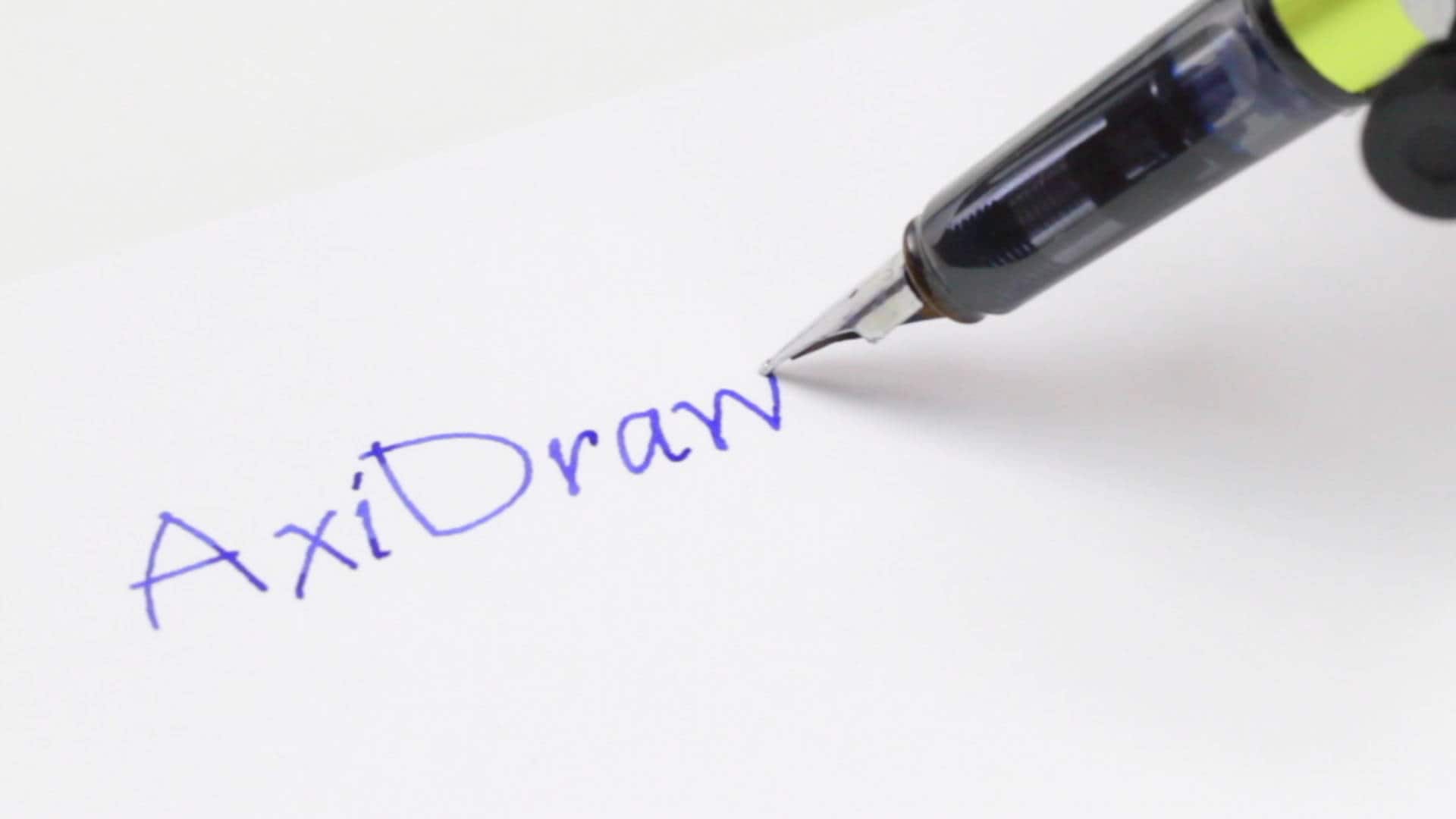 Simple, modern, and precise pen plottersAxidraw machines work with a variety of writing instruments, including permanent markers and fountain pens. the unique writing head extends beyond the base of the machine, making it possible to write or draw on almost any flat surface. axidraw is the real deal: designed, manufactured, and supported in usa, and backed by exclusive software for realistic handwriting and automation.. Watch the video > AxiDraw Models Compact and popular
 AxiDraw V3/A3Larger plot area.
 AxiDraw SE/A3Special edition.
Additional AxiDraw models and accessories are available at Evil Mad Scientist Where to buy AxiDrawAxiDraw machines are available for purchase directly from Evil Mad Scientist as well as from select distributors:  Frequently Asked QuestionsThe AxiDraw is a pen plotter, which is a type of simple robot. Its sole function is to guide a pen (or other implement mounted in the pen holder) along the set of vector lines, curves, and paths that you ask it to follow. Everything that the machine is ultimately capable of, such as drawing graphics, writing text, or signing documents, are expressions of this basic function. It is capable of drawing essentially anything that can be composed from a set of lines. In practice, this is much like using a traditional printer, except that you need to take care that your documents are made of paths, rather than pixels. The AxiDraw is an extremely versatile machine, designed to serve a wide variety of everyday and specialized drawing and writing needs. You can use it for almost almost any task that might normally be carried out with a handheld pen. AxiDraw does not require proprietary pens or ink: you can use your own pens, chosen within certain guidelines. AxiDraw can hold most types of pens and similar instruments up to 5/8" (16 mm) diameter. (A larger XL Pen Clip is available as well to fit larger pens.) Good choices for pens to use include fountain pens, permanent markers, liquid-ink rollerball pens, technical pens, small-bodied whiteboard markers and other writing and drawing instruments that do not require significant downward pressure. While we refer to writing and drawing instruments as “pens” to be concise, other instruments such as automatic pencils (particularly with soft lead), chalk, charcoal, and brushes can also work well in many cases. You can read more about pen choices in our documentation here . AxiDraw does not require special paper; you can use almost any kind and size of paper. (You can even use all kinds of things that are not paper.) The XY travel (printable area) of the AxiDraw V3 is just over that of both US letter (8½ × 11”) and A4 paper sizes. The larger size models have about twice this travel. You can work with any size of paper up to the size of the travel area. You can write directly onto small pieces like business cards (or a whole array of them), medium size pieces envelopes and note cards, or sheets of paper. You can also work with paper larger than the travel area. The unique design of the AxiDraw features a drawing head that extends beyond the body of the machine, making it possible to also draw on flat objects bigger than the machine itself. For example, you can set it right on top of a box to write an address. You can even set it on top of a poster board, chalkboard, or whiteboard to draw graphics in place. For most applications, the standard-size AxiDraw V3 is the best choice. It's compact so that it fits on your desk more easily, and has enough plotting area to cover any size up to 8½ × 11” / A4. The larger AxiDraw V3/A3 has twice the plotting area and is perfect for people who need to plot larger items, or to fit two smaller items — like two US Letter or A4 pages side by side, or a sheet of paper plus an envelope. The Special Edition AxiDraw SE/A3 has the same plotting area as the V3/A3, but features a heavy, rigid base CNC machined from a solid block of Aluminum. It's our top-of-the-line machine, and includes a few nice accessories as well. Available AxiDraw accessories include alternate pen holders, a tripod mount, a rigid mount that can be used instead of the pen slide, extended feet, extra clip easels, and magnetic workholding easels. You can find them listed here at Evil Mad Scientist. AxiDraw requires a reasonably modern computer (Mac, Windows, or Linux) with an available USB port and internet access to download software. Mac requirements: MacOS 10.7 or newer Windows requirements: Windows 7 or newer Linux requirements: Recent versions of Ubuntu and similar widely-supported distributions work well. If you are using an obscure or "challenging" distribution, we'll still do our best to help you out. No. All standard AxiDraw models (V3, V3/A3, SE/A3) come complete, assembled, tested, and ready to use. If you get a head start by reading the user guide and installing the software, you can be up and plotting five minutes after opening the box. If you prefer a model that requires assembly, there is now also AxiDraw MiniKit 2 which comes as a kit. Internet access is required only for downloading software and for access to online documentation. Internet access is not required while preparing files or using AxiDraw. A universal-input plug-in power supply is included with the AxiDraw. It accepts worldwide 100 V - 240 V input, and has a US/Canada style plug. For other regions, an inexpensive plug shape adapter will be needed. No. Most users just make a file or drawing and plot it. (That said, programming interfaces are available for those who are interested in them.) You do not need to purchase any additional software to use AxiDraw. AxiDraw is normally controlled through a set of extensions to Inkscape, the excellent, popular and free vector graphics program. Basic operation is much like that of a printer driver: you import or make a drawing in Inkscape, and use the extensions to plot your text or artwork. It's all handled through a straightforward graphical user interface, and works cleanly on Mac, Windows and Linux. Yes, and we highly encourage you to do so. Reading the manual is a great way to determine if AxiDraw is a good fit for you. The AxiDraw V3 family user guide is available for download here . Unlike a (raster-based) inkjet or laser printer, the time that it takes a plotter to print a page is not fixed. Rather, it depends on the length of distance that the pen has to travel. The AxiDraw typically moves at about the speed of a human hand, depending on your settings, and the plotting time varies accordingly. This question is much like asking how long a human takes to write or draw on a piece of paper: Addressing an envelope might typically take a minute or two, but complex artwork can potentially be a matter of hours. Such is the case as well for AxiDraw. Yes. The speed of the AxiDraw is adjustable, depending on your tradeoff between faster completion and higher precision. AxiDraw can move quite quickly (faster than a human normally can) when making large strokes with a wide-tipped marker, but even a (human) calligrapher will slow down for higher neatness. The wedding invitation text in our video should give you a decent idea of typical writing speed when going for higher neatness; that example is a little slower than people normally write. Yes! The best way to do that is by directly capturing your signature as you sign it, for example on a phone or tablet screen. That way, the AxiDraw can replay it just in the same way that you wrote it. Capturing a signature is covered in our documentation on handwriting, here . We also have exclusive utilities, available to AxiDraw owners, that can add handwriting-like "defects" to your text. Text laid out in perfectly even rows (like what you get with a handwriting font in MS word) always looks a little too "robotic" to be handwriting. No, not in the way that you might hope. Yes, you can scan handwritten text, trace it with a bitmap tracing tool, and plot it. This is straightforward, and your AxiDraw will be more than happy to comply. (AxiDraw will plot the paths that you provide to it.) However, and with only rare exceptions, automatic tracing of scanned handwriting creates a somewhat unpleasant imitation of handwriting, and we do not recommend this approach as part of any workflow. You can read more about tracing scans in our documentation, here . (In brief: there are excellent ways to use the AxiDraw to reproduce handwriting, but starting with a scan is not one of them.) Not at present, but it is something that we are looking into. Some AxiDraw users do use various types of paper handling machines — sometimes printers with built-in paper feeders and sometimes commercial solutions. Professional print shops and companies that make equipment for them have many different ways of moving pieces of paper from point A to point B. More commonly, for small scale use, AxiDraw users manually swap out paper clipped to small clipboard easels or use larger-size AxiDraw units that allow multiple pages to fit within the print area. Yes; you can see a few examples here . The key issues that you need to be aware of is that the fabric generally needs to be held taut, and you need to choose markers that don't easily catch on the fabric. It is likely that with care and experimentation you will be able to make it work. Calligraphy is not the same in any sense as (for example) simply using computer fonts or plotting a drawing. Calligraphy generally involves individually sculpted letter shapes, and in many cases pen movements that are far more complex than AxiDraw can provide. That said, some calligraphers do use AxiDraw for low-end busywork (say, addressing hundreds of place cards), saving some wear on their wrists and presumably passing along some of the cost savings. The AxiDraw is designed for moving a pen, not a carving or cutting tool. It does not have the type of rigidity that you need for carving, nor the ability to apply significant downward force. That said, a number of people have experimented with it. Here is one notable project, using the AxiDraw for cutting cardstock and vinyl. AxiDraw can be used with whatever fonts are on your computer, so long as the text is converted to paths before plotting. We have developed a special-purpose software application called AxiDraw Merge , which is a mail merge solution for AxiDraw. Once you are set up with it, AxiDraw Merge can automatically (1) populate a template with data sourced from a CSV file, (2) render the text into handwriting-like stroke-based fonts, (3) add intentionally variations so that text does not lie upon straight lines, and (4) plot the document. It can also merge and plot subsequent pages upon a button press or after a time delay. AxiDraw Merge is available to AxiDraw owners at no additional cost. The AxiDraw is designed to work on flat surfaces, and we do not test them in the vertical orientation. That said, quite a few AxiDraw users have mounted theirs to the wall without apparent difficulty. One issue to consider is that the AxiDraw's pen holder normally rests the pen on the writing surface by its weight alone. On the wall, you'll need an alternative to gravity for lowering the pen. The typical solution is a rubber band. (1) We maintain a large and growing library at the AxiDraw Wiki Page , our central documentation site for all things AxiDraw. Our documentation is clear and comprehensive, with special sections to help you get up and running quickly. (2) We have support forums for the AxiDraw, here . (3) Most importantly: We're the designers and manufacturers of the AxiDraw, and we're here to help! Please don't hesitate to contact us directly. AxiDraw does not have a duty cycle limit. You can run it all day long if you like. The AxiDraw is designed to be serviceable for a long life. Components such as the drive belt, rolling wheels, ball bearings, and stepper motors can all be replaced in the unlikely event that it should become necessary. (And, those parts are actually available if you need them.) One component on the AxiDraw is considered expendable and may need regular replacement in heavy duty (e.g., industrial) settings. The small pen-lift servo motor does wear out over time but is inexpensive and straightforward to replace. For heavy duty applications, you may wish to keep a spare on hand. We do also offer a performance upgrade option to a long-lasting brushless pen-lift servo motor , which also gives the AxiDraw a major speed boost. No. While AxiDraw is most commonly controlled through a set of extensions to Inkscape, there are other methods of plotting including the command-line interface (CLI). Many AxiDraw users do their design work in other programs, and use Inkscape as their "page setup" screen for plotting. For real-time plotting in response to user input and for certain other generative applications, you can plot directly within Processing . AxiDraw machines are designed, manufactured, and tested right at our facility in Sunnyvale, California. Demos are available by appointment at our shop in Sunnyvale, CA. Please contact us to request an appointment. We're open M-F, 12-6, and closed on US postal holidays. The AxiDraw has two precision stepper motors in its base. Together, they drive a single looped belt that moves the carriage around in the XY plane. The high-performance linear stages feature custom-designed wheels that roll smoothly on custom aluminum extrusions, specially designed for high stiffness and light weight. The pen-lift stage uses a separate mechanism: a smaller third motor, combined with a precise low-friction linear stage, serves to lift the pen off of the page. In addition to the popular AxiDraw models listed above we do make a few other standard sizes, as well as custom-sized and custom-configured AxiDraw machines. One notable version is the compact AxiDraw MiniKit 2 which comes as a kit. If you need a compact AxiDraw that is not a kit, we do make an AxiDraw V3/B6 (with plot area of 190 × 140 mm, or 7.48 × 5.51 inches) that is available by special order. We also make larger format and customized AxiDraw machines to order, including the AxiDraw SE/A2 and SE/A1 with plot area of 594 × 432 mm (23.4 × 17 inches) and 864 × 594 mm (34 × 23.4 inches), respectively. These larger machines typically require a custom shipping quote. No; we do not offer any printing services. Please contact us and ask; we're here to help. Support ResourcesOur AxiDraw documentation wiki is a continually growing library of resources for getting started with the AxiDraw, including a thoroughly detailed PDF user guide , support forum, a number of tutorials on specialty topics, and links to additional resources. Personal support: We're here to help!Having an issue? Need to know where to find something in the manual, or how to do something that isn't in the manual? Want to ask us about your application before deciding to purchase? If so, please don't hesitate to contact us directly. Our goal is to provide personal, competent service both as you get set up and running, and for as long as you have your AxiDraw.  DIY CNC Writing Machine Using GRBL Introduction: DIY CNC Writing Machine Using GRBL In this project, I will show you how to easily build your own low-cost Arduino CNC Plotter Using Free and Open-Source Software! I’ve come across a lot of tutorials explaining how to build your own CNC plotter, but not a single one that explains in detail about all the details and software required to make it happen. I had to cross-refer with a hell lot of tutorials to make this project happen. Everything including the details of the software used are mentioned in this tutorial. Thus, I wanted to share this with the society for anyone who wishes to create this Project. Step 1: WHAT YOU’LL NEED
Step 2: BASIC OVERVIEWThe heart of this machine is the Arduino working with the CNC Shield and the Stepper Motors. The stepper motors are used to actuate the X and Y axes. Two gantries each consisting of one stepper motor is made and constructed using acrylic. Each axis is controlled separately by the Arduino running the GRBL Firmware which is free and open-source. The pen attached on the Z-Axis is controlled using a servo. Step 3: MAKING THE FRAME Download the given Illustrator file and use your respective Mill/LaserCutter/3D Printer to make the pieces for the frame. Also cut out the supports for the Stepper motor. AttachmentsStep 4: creating the adapter for the motor.  I 3D modeled the adapter for the model in Fusion 360 according to the dimensions of my rod and motor shaft. The stl and fusion files are linked down below. It can also be found on my TinkerCAD profile. Download the files and 3D print the Adapter. Click here for the TinkerCAD file.  Step 5: ASSEMBLING THE GANTRIES
Step 6: MOUNTING THE GANTRIES ON TOP OF EACH OTHER Slide-in nuts on both the threaded rods and the plain rods and fix them in place. Glue a piece of acrylic spaning over both the rods. Glue the Y axis gantry to this piece of acrylic, Step 7: MAKING THE PEN HOLDER CNC out the required parts and put them together to form the mechanism shown in the images. Attach the Servo in the given spot using glue. Step 8: WIRING THE MACHINE Connect the male jumpers in between the Driver holders to enable micro-stepping. connect the rest of the parts as mentioned in the wiring diagram. Power the parts using a 12v supply Step 9: REFER THE VIDEO BY CREATTIVE BUZZ FOR CLEARER DETAILS ON THE MECHANICAL CONSTRUCTIONI've done my Mechanical construction all in reference to this video, all credits to the owner. Step 10: SOFTWAREStep 11: flashing grbl to the arduino. The main Software running on the Arduino that controls the Motors is GRBL. TO flash it :
Step 12: INKSCAPE FOR SENDING THE GCODE Download Inkscape Version 0.47 from here . and install it. Step 13: DOWNLOADING AND ADDING THE GRBL EXTENTION TO INKSCAPEDownload the below-given files Refer to this video for details on how to install the extension in Inkscape. Step 14: UNIVERSAL G CODE SENDERDownload the Universal G Code sender and unzip it. FROM HERE . Step 15: CALIBRATING THE STEPS PER MM FOR G CODE SENDER Open the G-Code Sender aplication.
Step 16: Creating the GCODE FILE
SIT BACK AND LET THE MACHINE DRAW.  Participated in the CNC Contest Recommendations Puzzles and Games Contest Pets and Animals Contest Make it Resilient | |||||||||
IMAGES
VIDEO
COMMENTS
DIY Homework Writing Machine: In this Instructable, I'll show you how to create a completely functional 3D-printed writing machine for your science fair project at school or college. This project was created as part of my second-year engineering project at Gujarat's Chandubhai S…
Get (1) Hex M3-0.5 x 20mm screw and the Metric Thumb Screw and push them together. Use superglue to keep it together. Get (3) M3-0.5 x 16mm screws which you will use the secure the Base Slide to the Y-Front part. You may need to use (3) M3-0.5 nuts in order to hold it in place.
Make DIY Homework Writing Machine at Home: Drawing Robot/Pen Plotter/Drawing Machine is an Open Hardware version of the famous machine AxiDraw which it is a pen plotter, capable of writing or drawing on almost any flat surface. It can write with pens, permanent markers, pencils, and other wr…
Step 1: Assembly - Y Axis. Take the 2040mm profile and attach the base plates to both the ends. Use the sliding nuts and m4 bolts to attach the base plates to the profiles. Now turn the profile and attach rubber feet to the bottom slots of the base plates. These rubber feet will hold the machine in place on smooth surfaces.
In this video we make homework writing machine using Arduino uno and stepper motors.This writing machine can be used for writing and drawing in science proje...
This is the Version 2.0 of the Arduino Homework Writing Machine - 2D CNC Plotter. this version comes with a lot of upgrades from the previous one, which incl...
How to Make Homework Machine at homeLearn How to make homework writing and drawing machine at home using Stepper motor.You can make this type of automatic wr...
Get (2) 3mm linear rods and the following 3D printed parts (Slider, Pen Holder, Base Slide, 3MM Metric Thumb Screw) Get (1) Hex M3-0.5 x 20mm screw and the Metric Thumb Screw and push them together. Use superglue to keep it together. Get (3) M3-0.5 x 16mm screws which you will use the secure the Base Slide to the Y-Front part.
Homework writing machine project description: Servo Motor: A servomotor is a rotary actuator or linear actuator that allows for precise control of angular or linear position, velocity and acceleration.It consists of a suitable motor coupled to a sensor for position feedback. It also requires a relatively sophisticated controller, often a dedicated module designed specifically for use with ...
Learn how to build a DIY Arduino Writing/Drawing Machine - 2D Pen Plotter with this tutorial video. See the machine in action and get the code and schematics.
Take the (2) 350mm linear rods and insert them the Y-back piece by using a rubber mallet. Get (1) M4-0.5 x 35 screw, (1) M4 nut and the 5th 624zz bearing. Get (2) M3-0.5 x 16 screws to secure the linear rods. Slide in the bearing when inserting the screw through the Y-back piece. Y-Front.
Get (1) Hex M3-0.5 x 20mm screw and the Metric Thumb Screw and push them together. Use superglue to keep it together. Get (3) M3-0.5 x 16mm screws which you will use the secure the Base Slide to the Y-Front part. You may need to use (3) M3-0.5 nuts in order to hold it in place.
This homework writing machine project features a DIY writing machine that uses a typical pen. It can do outline writing and digital signature or even a real text. The main system uses a 2 axis stepper motor driver board with Nema stepper motors and Mg90S Metal Gear Servo control. The 2 axis stepper motor driver board serves as the main controller.
DOWNLOAD OUR NEW APPLICATION TO GET ALL SCIENCE DIY PROJECTS AT ONE PLACE.TO DOWNLOAD CLICK BELOW. CLICK HERE >>>>>DIY PROJECTS Hi guys , As per the title this is a simple project using Arduino to make Homework writing machine at your home.This machine can draw any design and write any type of fonts.You can see sharpness and perfection of writing in photos.
This Drawing Robot/Pen Plotter/Drawing Machine is similar to the commercially available AxiDraw. It is powered by an Arduino Uno controller, uses a CNC Shiel...
The document describes how to build a DIY homework writing machine at home. It can be used to write or draw on surfaces larger than the machine itself using pens, pencils or other writing implements. The machine uses an Arduino Uno controller and CNC shield to control two Nema 17 stepper motors that move a writing head along an X-Y axis. It can be built for around $75 and has a maximum drawing ...
Step 2: Building X and Y Axis Carriages. Take out the stepper Motor from dvd writer as in the picture. You need to open 2 dvd writers carefully without damaging anything inside it. Screw one carriage which contained the stepper motor to the 1ft.x1ft. board, this is the X-axis motor carriage. Keep some gap for Y axis motor carriage to be placed ...
How to make Homework Writing Machine at homeFiles: https://goo.gl/uCwzvRUNO R3 Arduino: https://goo.gl/bpbfJiArduino CNC Shield V3: https://goo.gl/VzsXqh3D P...
Simple, modern, and precise pen plotters. AxiDraw machines work with a variety of writing instruments, including permanent markers and fountain pens. The unique writing head extends beyond the base of the machine, making it possible to write or draw on almost any flat surface. AxiDraw is the real deal: Designed, manufactured, and supported in ...
Hello Friends, in this video i will show you DIY EleksDraw XY Plotter Pen Drawing Writing Robot Drawing Machine.It is an extremely versatile machine, designe...
Step 4: ATTACHING THE ELECTRIC MOTOR. Attach to Electric motor to the base of a Tie rod, reference the image. Make two of these. This will serve as the medium of moving the machine. Make sure the wheels of the electric motor directly fits in on the tie rod attached to the ply wood and ensure its free movement to and fro the surface.
🔗Product Links:Easydraw v3 - https://shopmakerq.com/product/easydraw-v3-writing-and-drawing-machine-fully-assembled/Inkscape Software Tutorial - https://you...
Step 16: Creating the GCODE FILE. Open Inkscape. Import the desired image and convert it to path. In Extensions, Use the MI GRBL EXTENSION. Press apply and create the GCODE FILE. Open File mode in GCODE Sender. choose the file. hit send. SIT BACK AND LET THE MACHINE DRAW.